
Table of Contents
Naked Mission 1 Pro DIY Manual
General Information
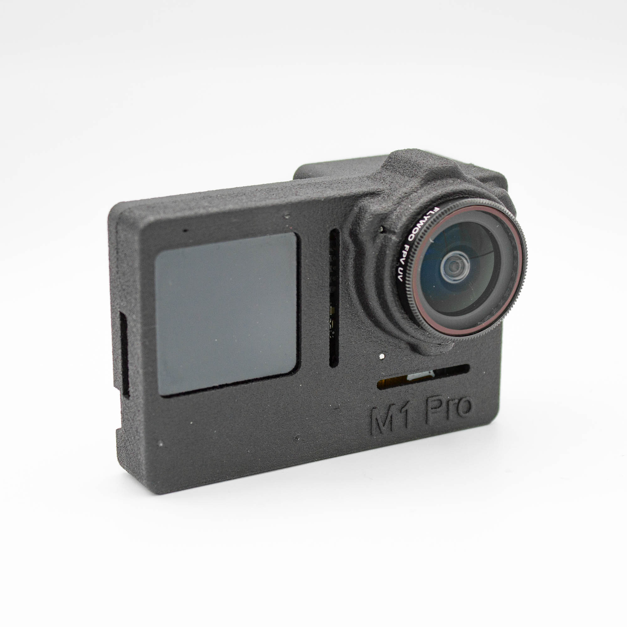
This manual shows you how to remove the original housing from your GoPro Mission 1 Pro (M1P) and assemble it in the FPVFrame.ch Naked Mission 1 Pro case.
This modification is for advanced users only. You risk permanently damaging your camera during disassembly and assembly. Read the entire manual before starting, prepare all required tools, and take your time.
Keep the original screws organized during disassembly. One of the original mainboard screws will be reused to secure the microphone FPC in the new case.
Happy building! If you are unsure about a step, contact support before continuing.
Content of Shipment
[TO CONFIRM: Final kit contents, including threaded insert sizes and whether the clear UV filter is included.]
The following parts and hardware are used during assembly:
- 1x Front case
- 1x Back case
- 1x 3D printed front display mount
- 1x 3D printed BEC holder
- 1x FPVFrame.ch custom FPC
- 1x FPVFrame.ch custom BEC
- 1x Cooling fan
- 1x Light pipe
- 4x Threaded inserts
- 1x Compatible clear UV protection filter
- 4x M1.4 x 3mm screws
- 3x M1.4 x 4mm screws
- 2x M1.4 x 6mm screws
- 3x M1.6 x 6mm screws
- 5x M1.6 x 8mm screws
- 1x M1.6 x 18mm screw
- 2x M2 x 5mm screws
You will also reuse one original mainboard screw for the microphone FPC.
Tools Needed
- Precision screwdriver set with suitable Phillips, Torx, and hex bits
- Cutter knife
- Fine flush cutters
- Thin plastic opening tool
- Plastic spudger
- Tweezers
- Pliers
- Hot air gun with adjustable temperature
- Soldering iron
- Solder
- Kapton tape or suitable electrical insulating tape
- Soft, lint-free cloth
- Small containers for organizing screws
- Smoke stopper for the first power-on
[TO CONFIRM: Exact screwdriver bit sizes.]
Download Files
[TO CONFIRM: Add the download link for the Mission 1 Pro printed parts.]
Safety Information
- Power off the camera and remove the battery and microSD card before disassembly.
- Wear eye protection when cutting or trimming parts. Keep your hands clear of the blade.
- Apply heat gradually. Excessive heat can permanently damage displays, ribbon cables, and plastic parts.
- Use plastic tools around circuit boards and connectors wherever possible.
- Never pull on a ribbon cable to disconnect it. Release the connector itself.
- Solder in a well-ventilated area or use fume extraction.
- Keep all power disconnected while soldering or connecting ribbon cables.
Preparation
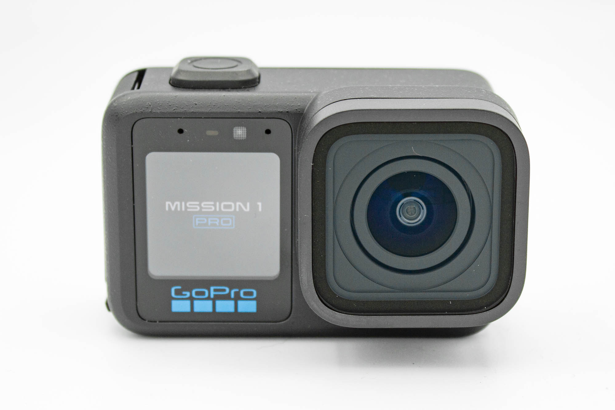
- Update your Mission 1 Pro to the latest GoPro Labs firmware available for your camera model.
- Complete the firmware update before starting disassembly.
- Power on the camera and check that it records correctly and that both displays work.
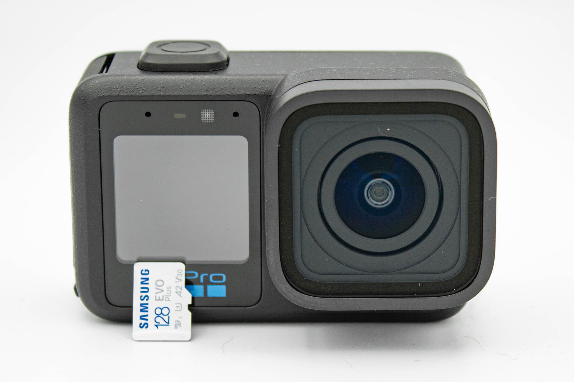
- Power off the camera.
- Remove the battery and microSD card.
- Disconnect any external power cables.
Disassembly Steps
Step - Release the Back Display
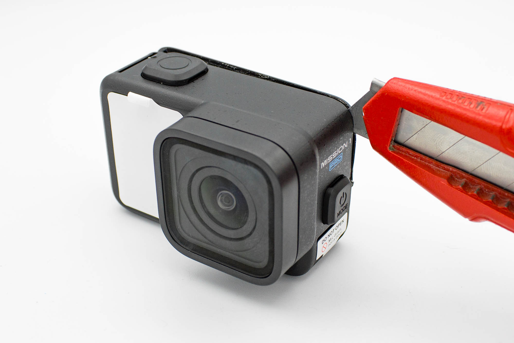
- Gently preheat the edges of the back display with a hot air gun to soften the adhesive.
- Insert the tip of a cutter knife into the seam between the back display assembly and the housing.
- Carefully cut through the adhesive along the edges.
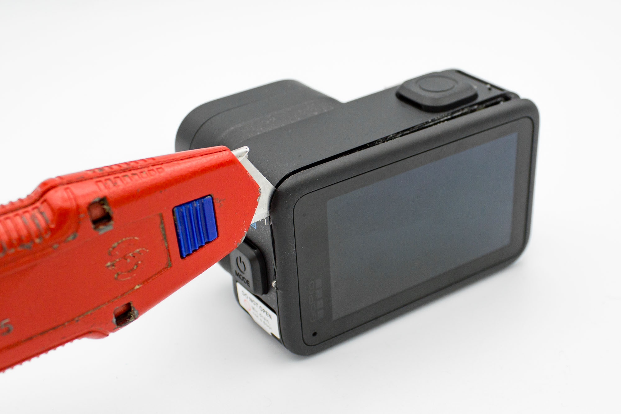
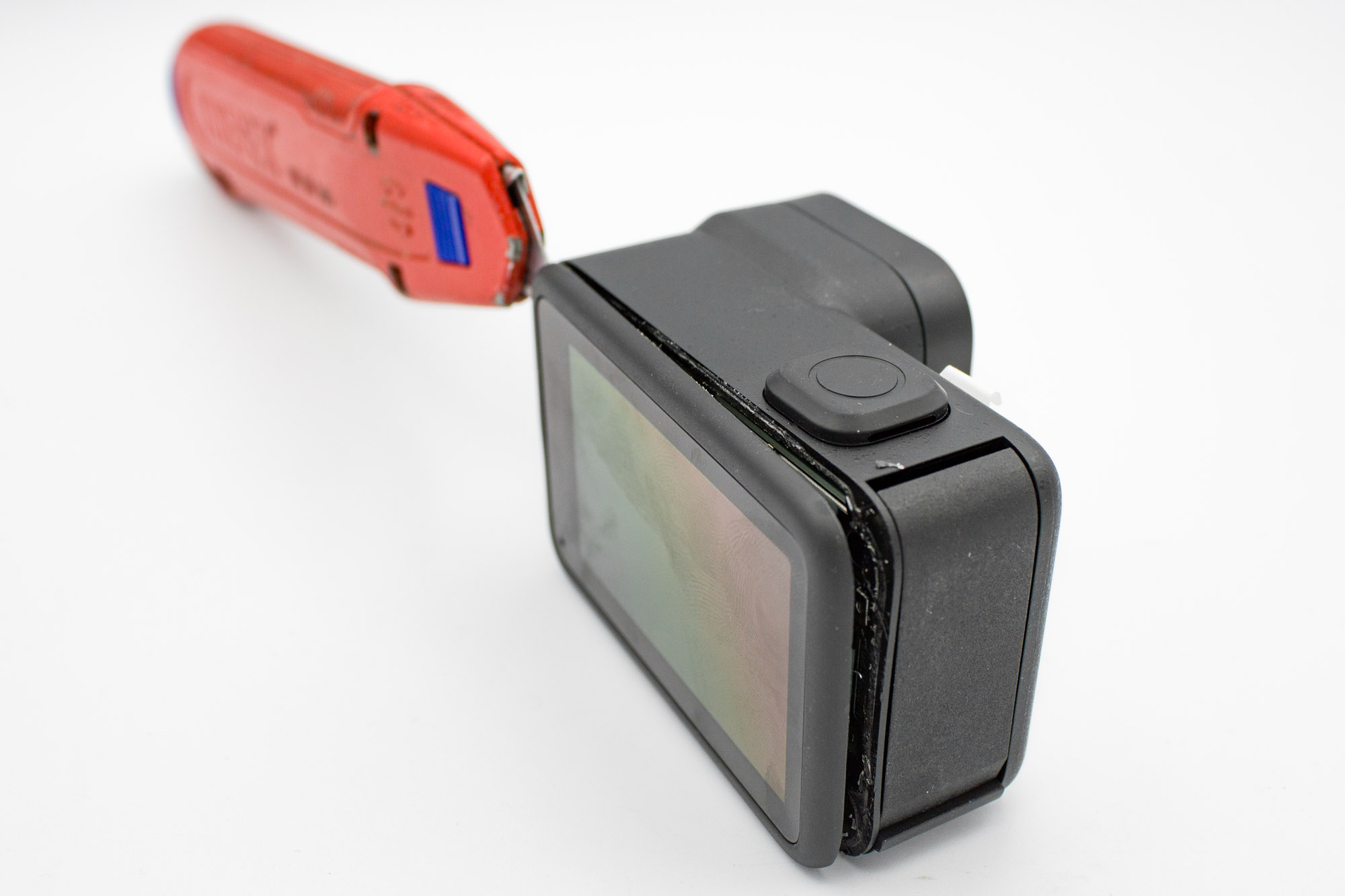
- Work gradually around the display until the adhesive releases.
- Keep the blade shallow. There is clearance behind the edges, but inserting the knife too far can still damage internal parts.
- Apply a little more heat if necessary instead of forcing the display away from the housing.
Step - Disconnect the Back Display
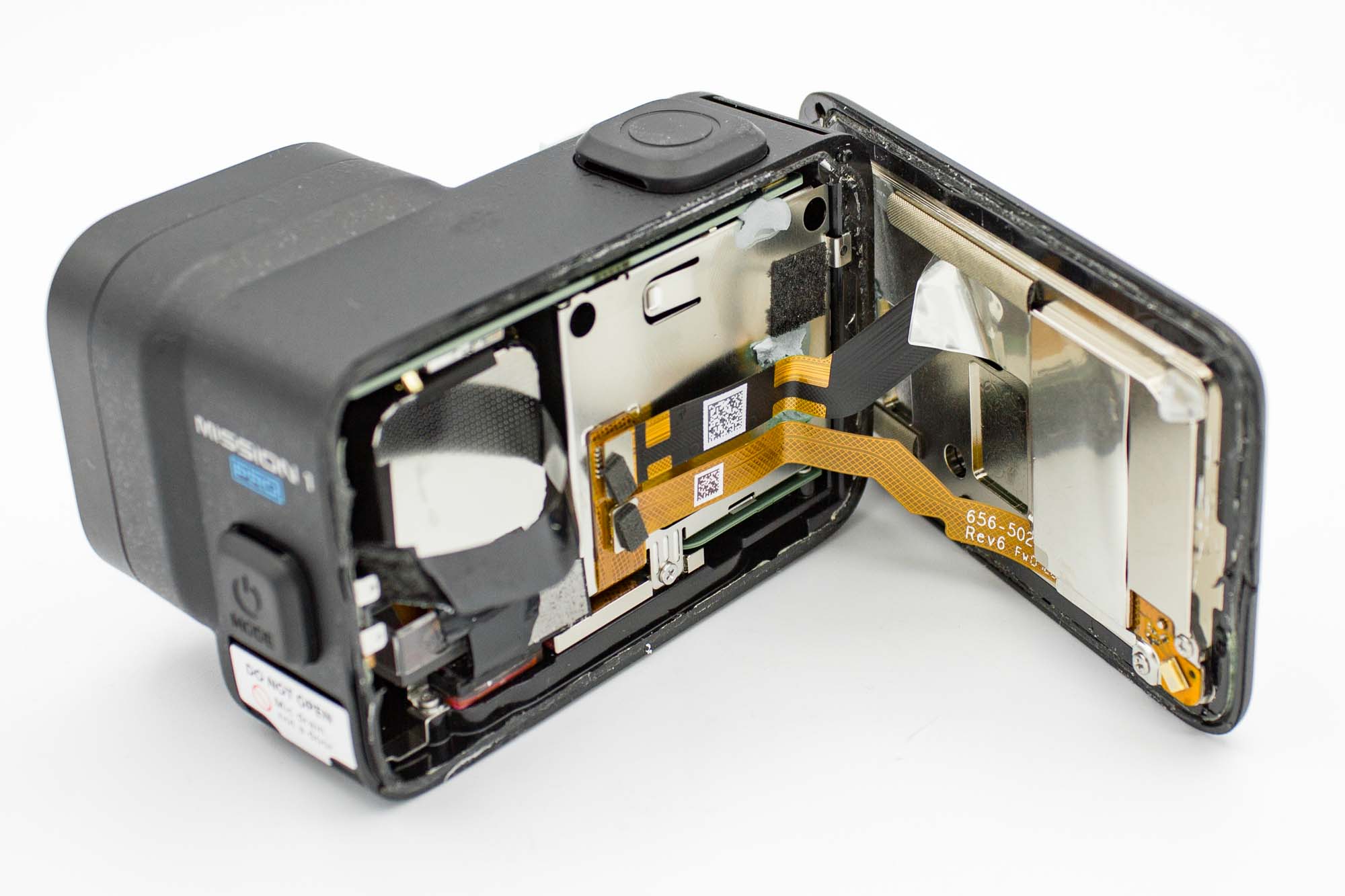
- Carefully fold open the back display.
- The two ribbon cables are long enough to fold the display fully open. Support the display so its weight does not pull on the cables.
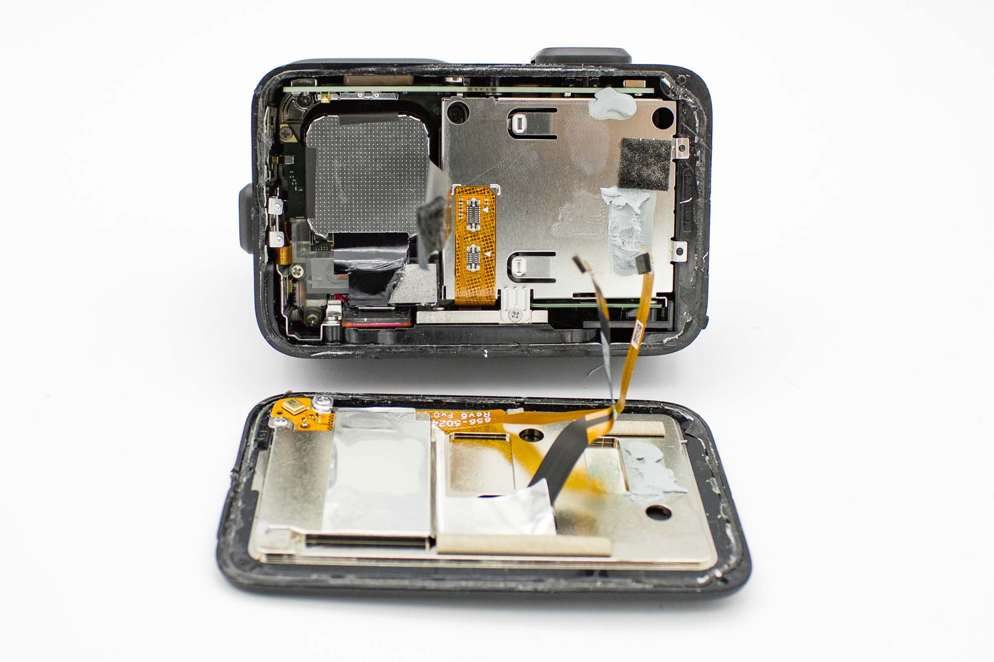
- Gently disconnect both ribbon cable connectors using a plastic tool.
- Remove the back display and set it aside.
Step - Remove the Battery Bay
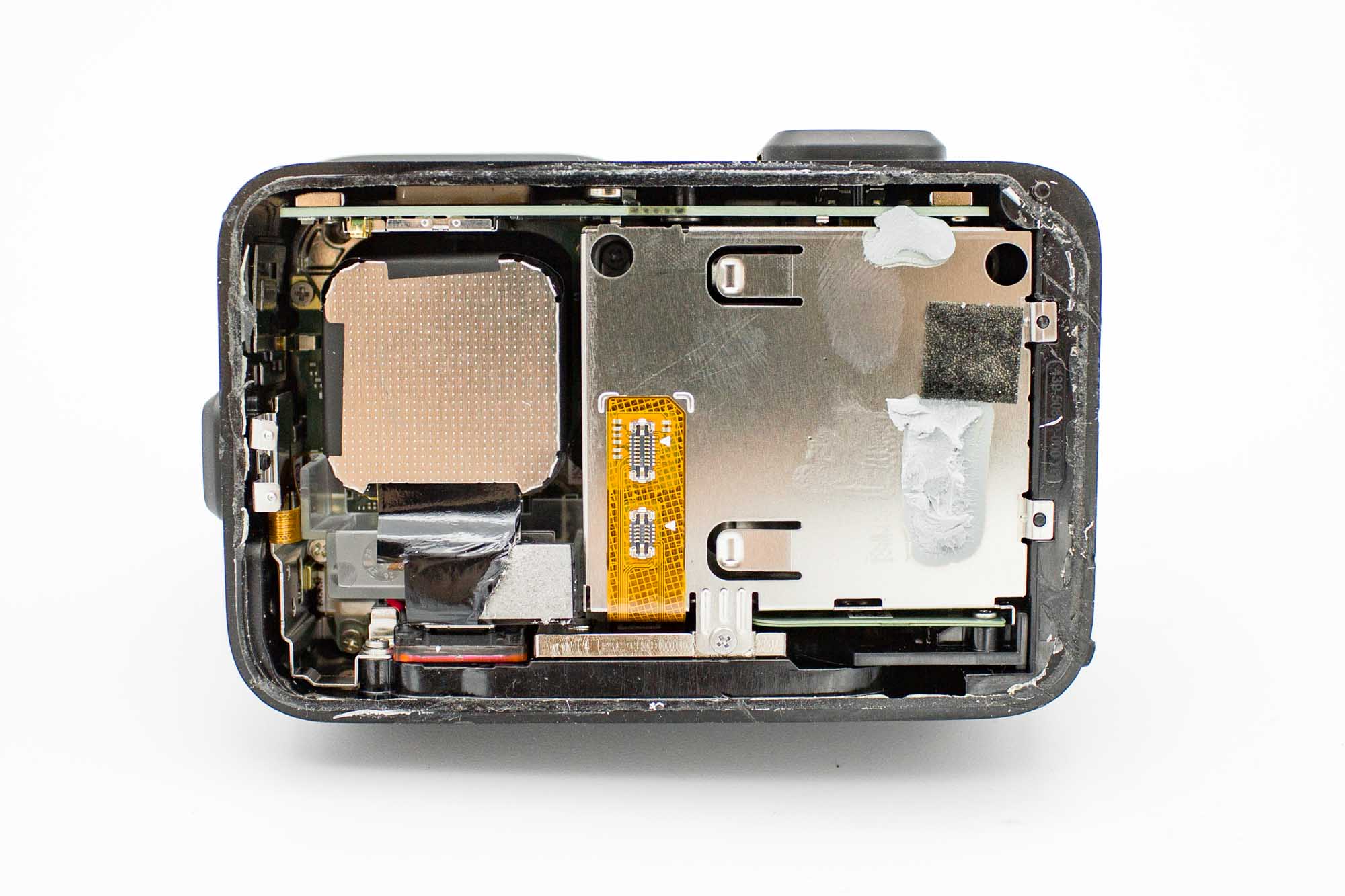
- Remove the three screws securing the battery bay.
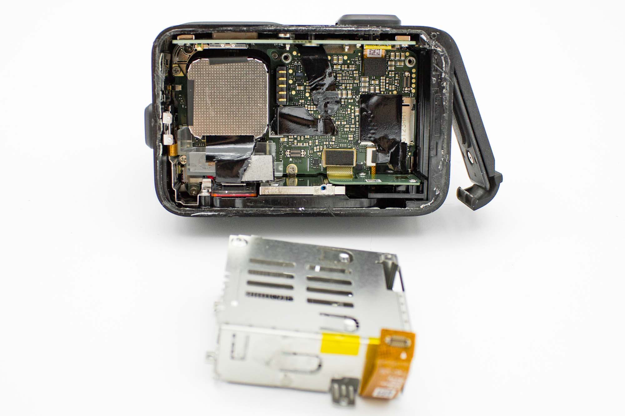
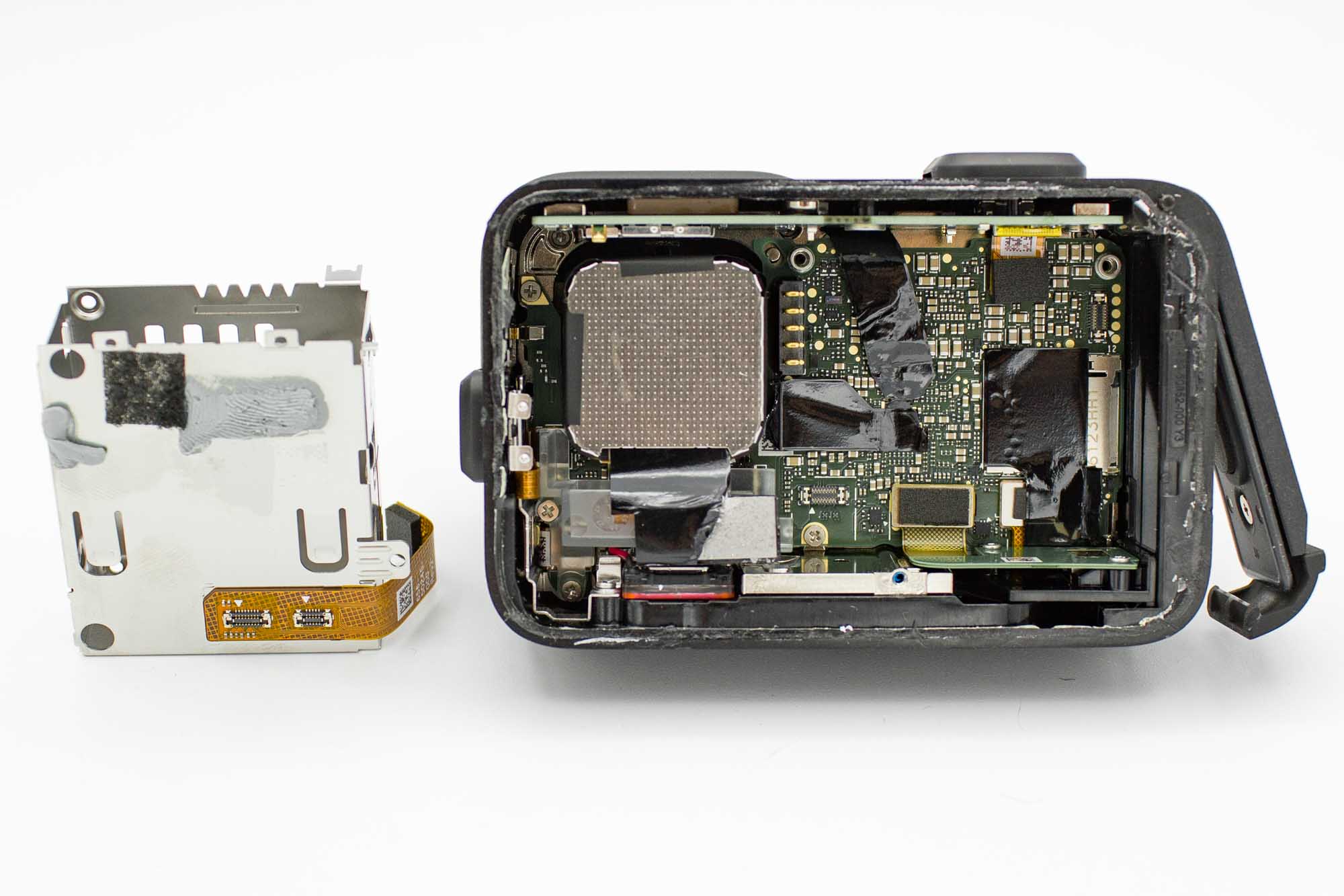
- Gently push the battery bay away from its installed position and lift it out.
- Guide its ribbon cable clear of the surrounding parts.
Step - Remove the White Plastic Bracket
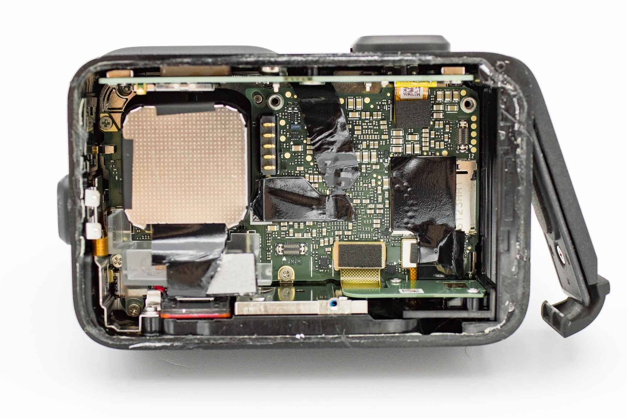
- Remove the two screws securing the white plastic bracket in the lower left corner.
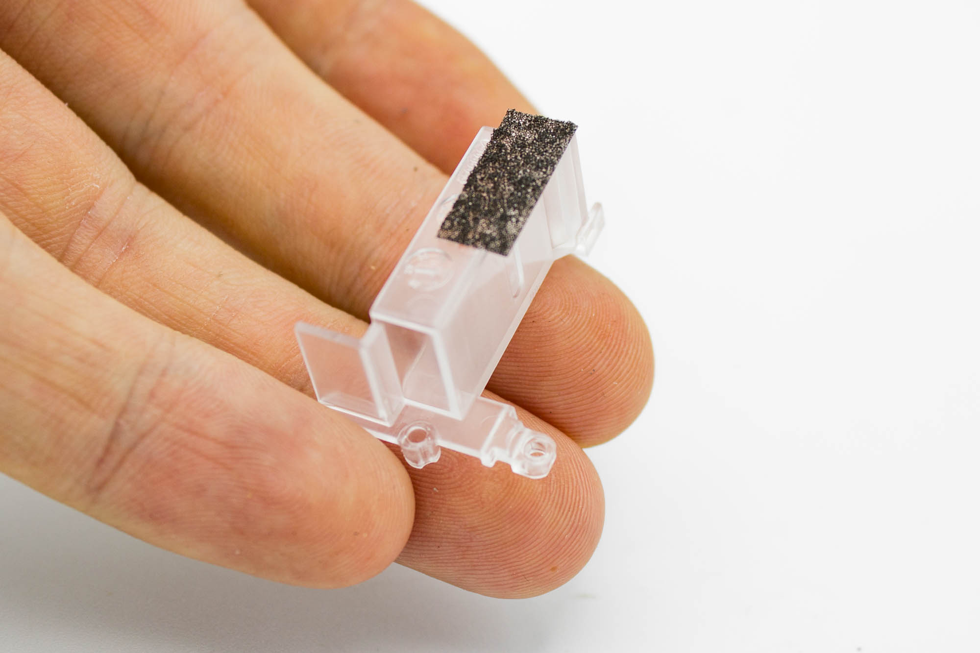
- Pull the bracket away and set it aside.
Step - Disconnect the Mainboard Cables
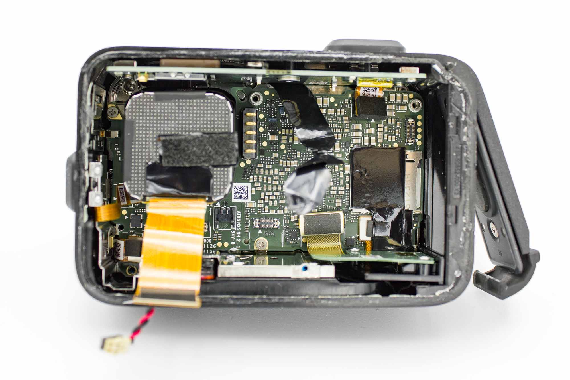
- Carefully peel back the tape covering the ribbon cable connectors.
- Disconnect the GPS board, USB assembly, sensor, power button, microphone assembly, and front display from the mainboard.
- Disconnect the speaker plug as well.
- Lift each press-fit connector gently with a plastic tool. Do not pull on the ribbon cables or wires.
- Move the disconnected cables clear of the mainboard.
Step - Remove the Lens Assembly
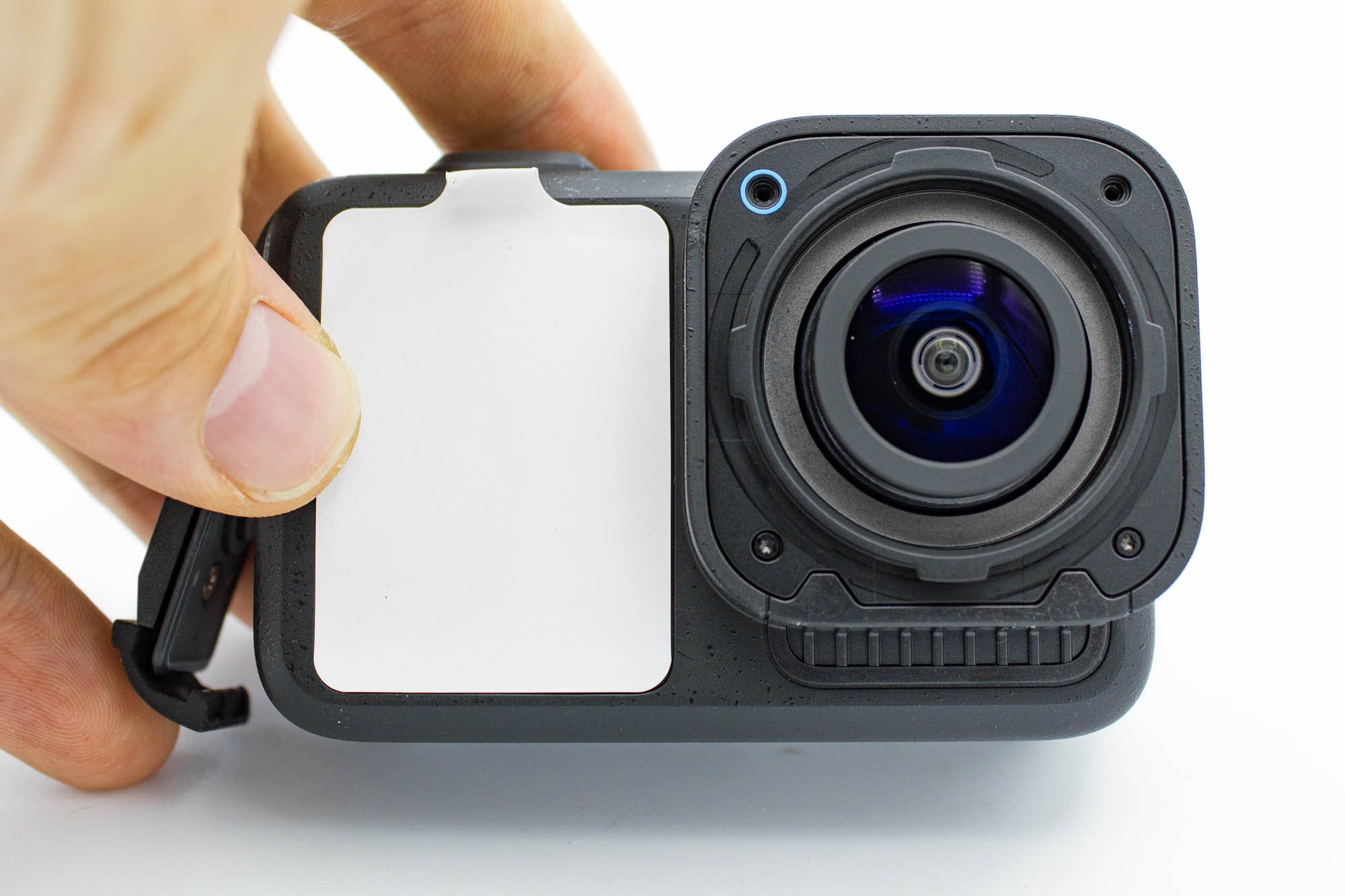
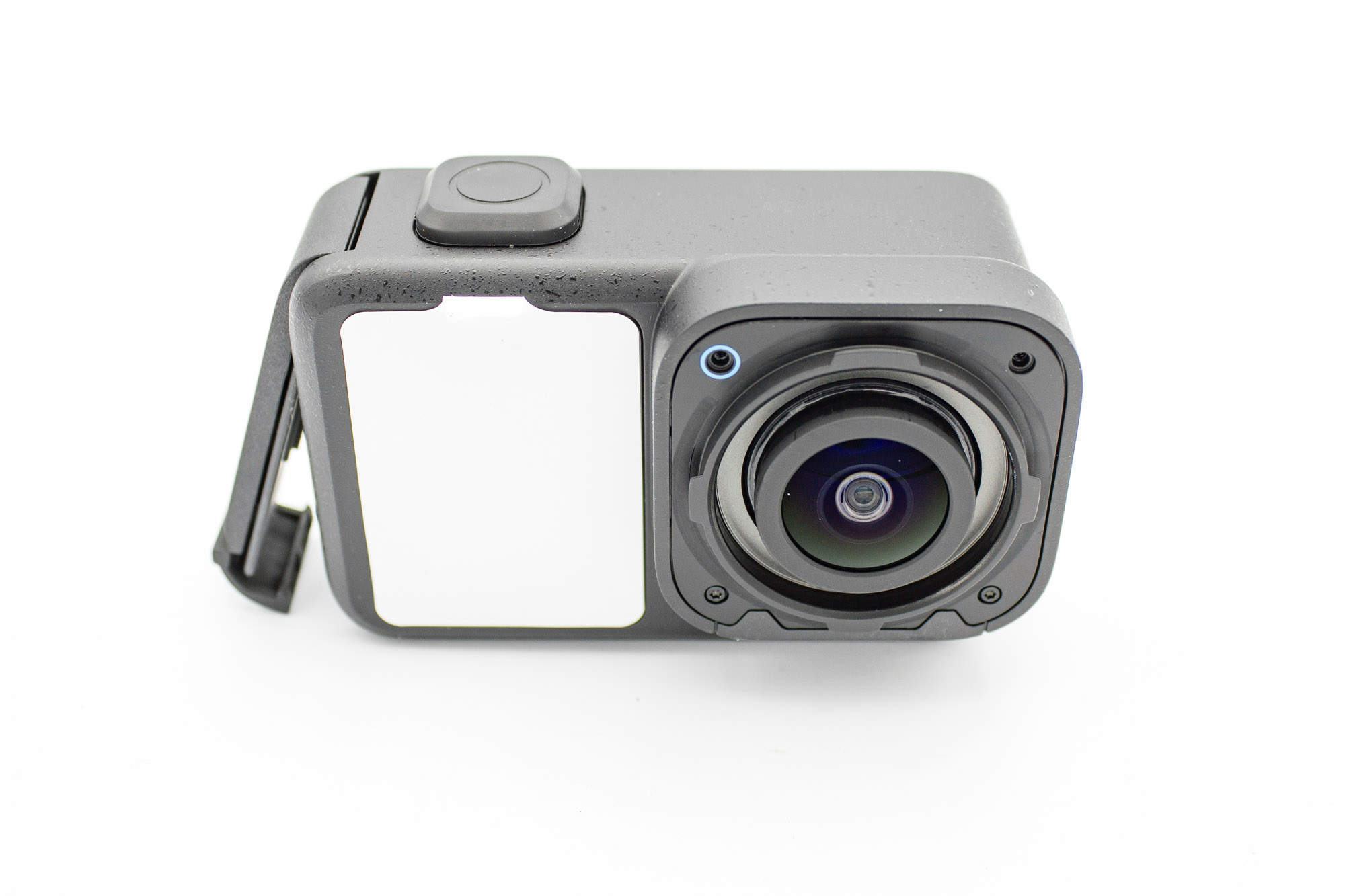
- Remove the lens protection ring to expose the four screws around the front of the lens.
- Remove all four screws.
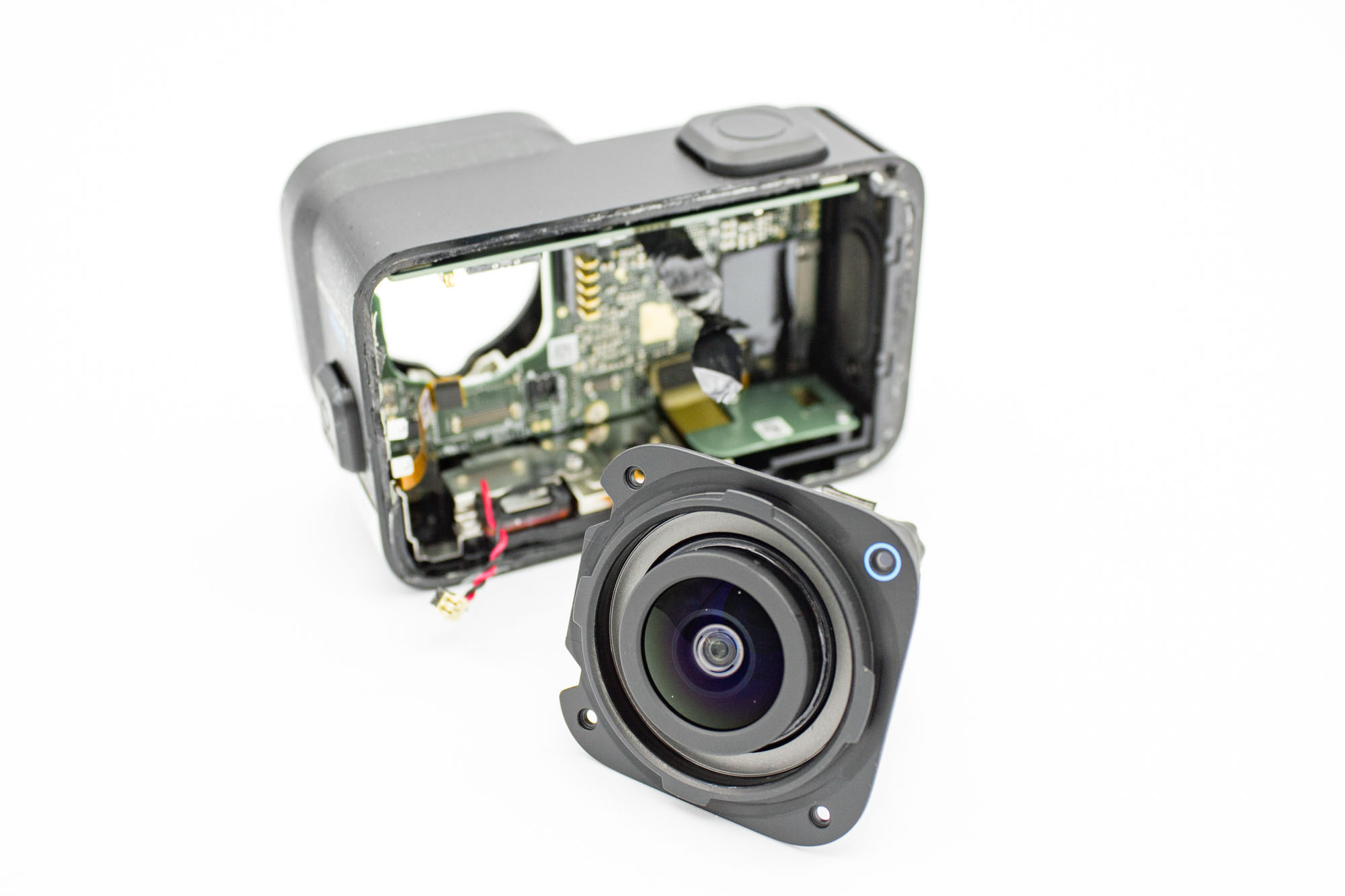
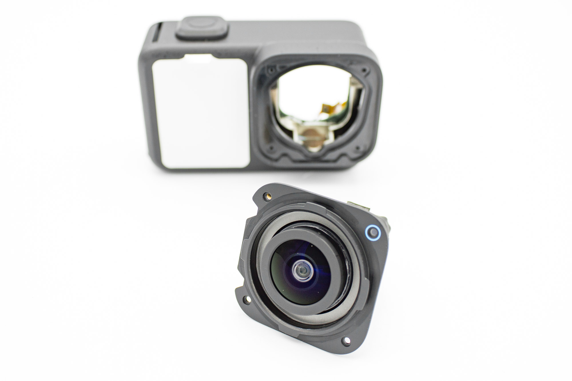
- Make sure the sensor ribbon cable is disconnected.
- Carefully withdraw the lens assembly towards the front of the camera.
- Guide the ribbon cable through the opening without catching it on the housing.
- Set the lens assembly aside on a clean, soft cloth.
Step - Remove the USB Assembly
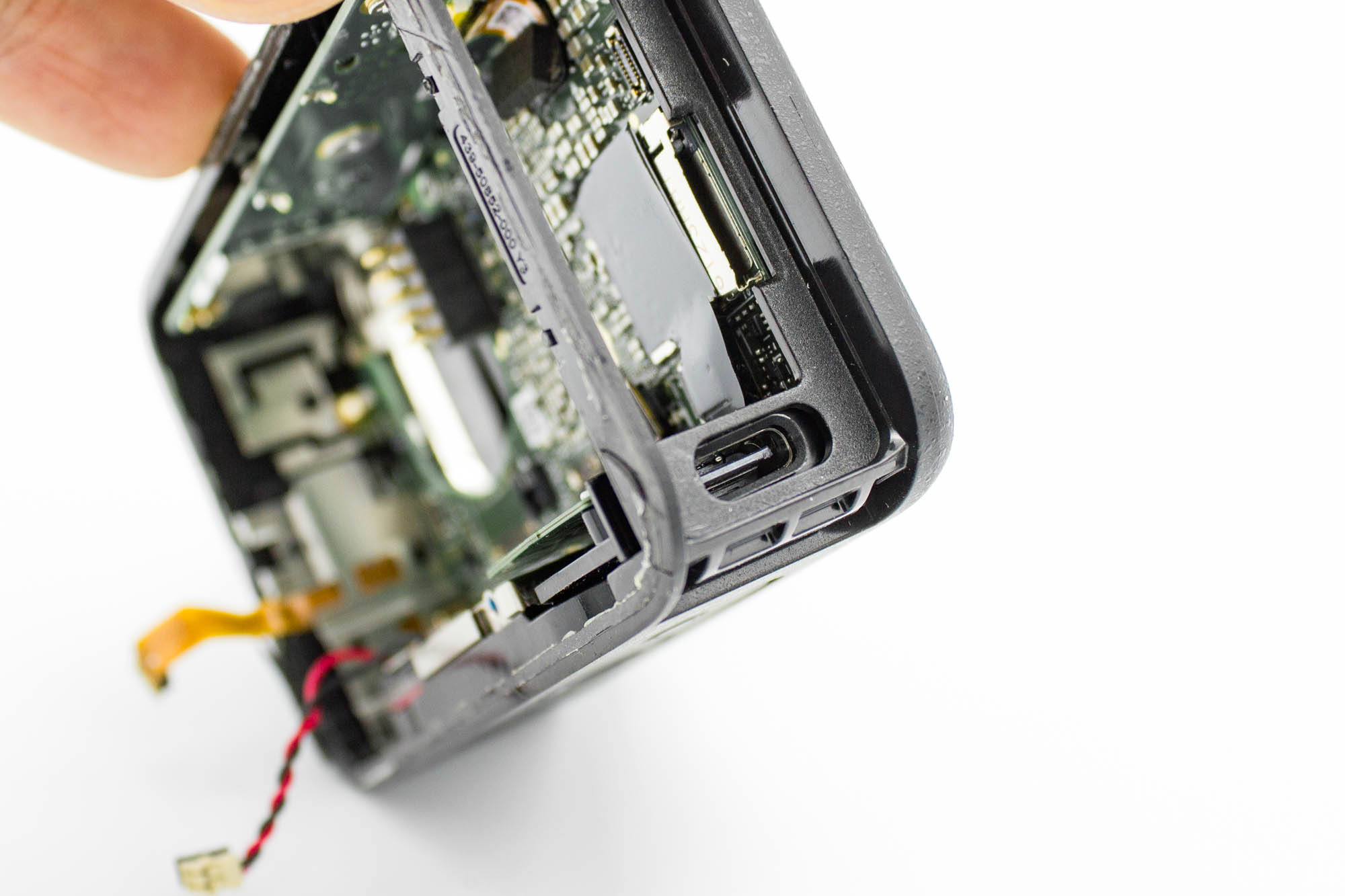
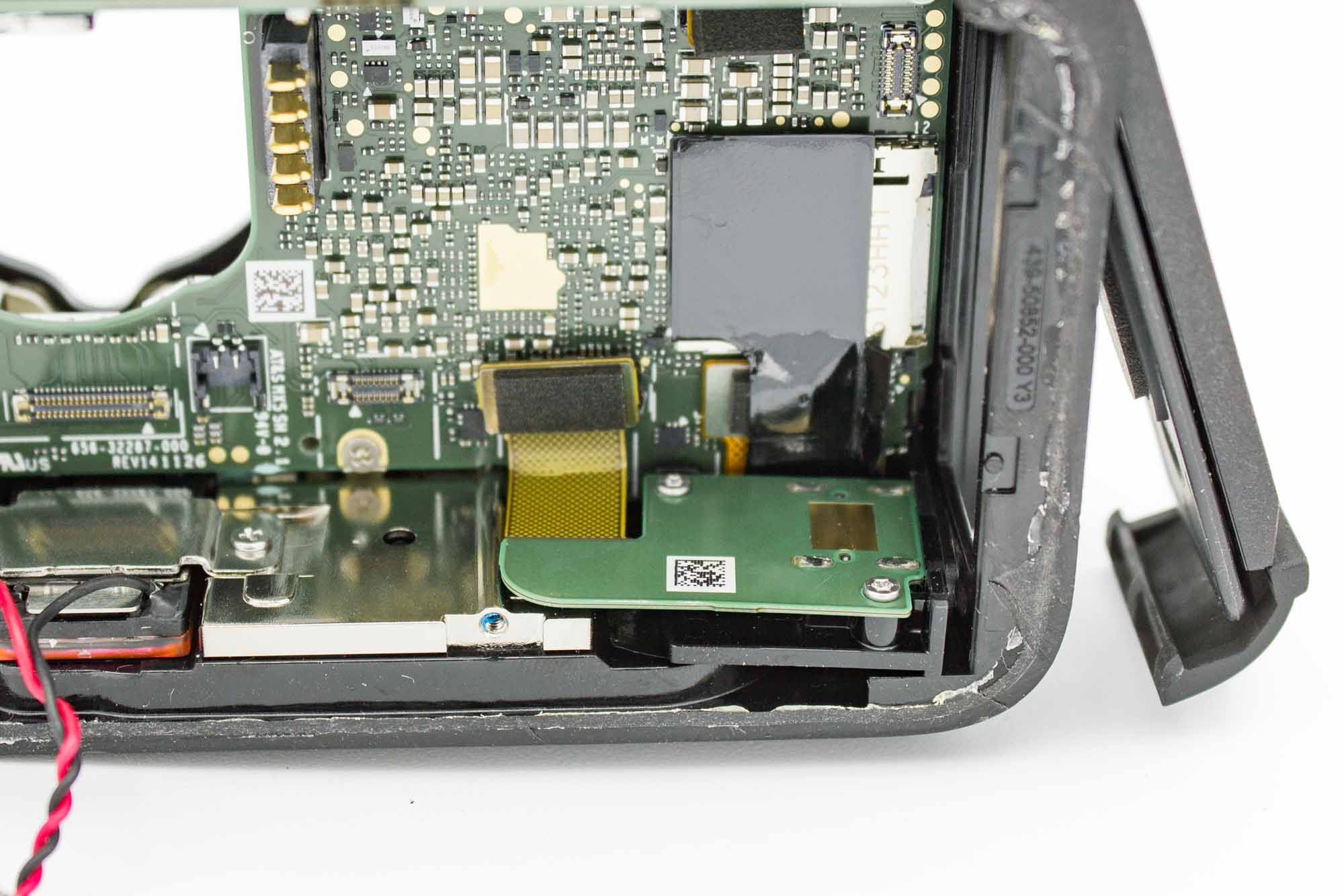
- Make sure the USB ribbon cable is disconnected from the mainboard.
- Gently push the USB assembly inwards to release it from the housing.
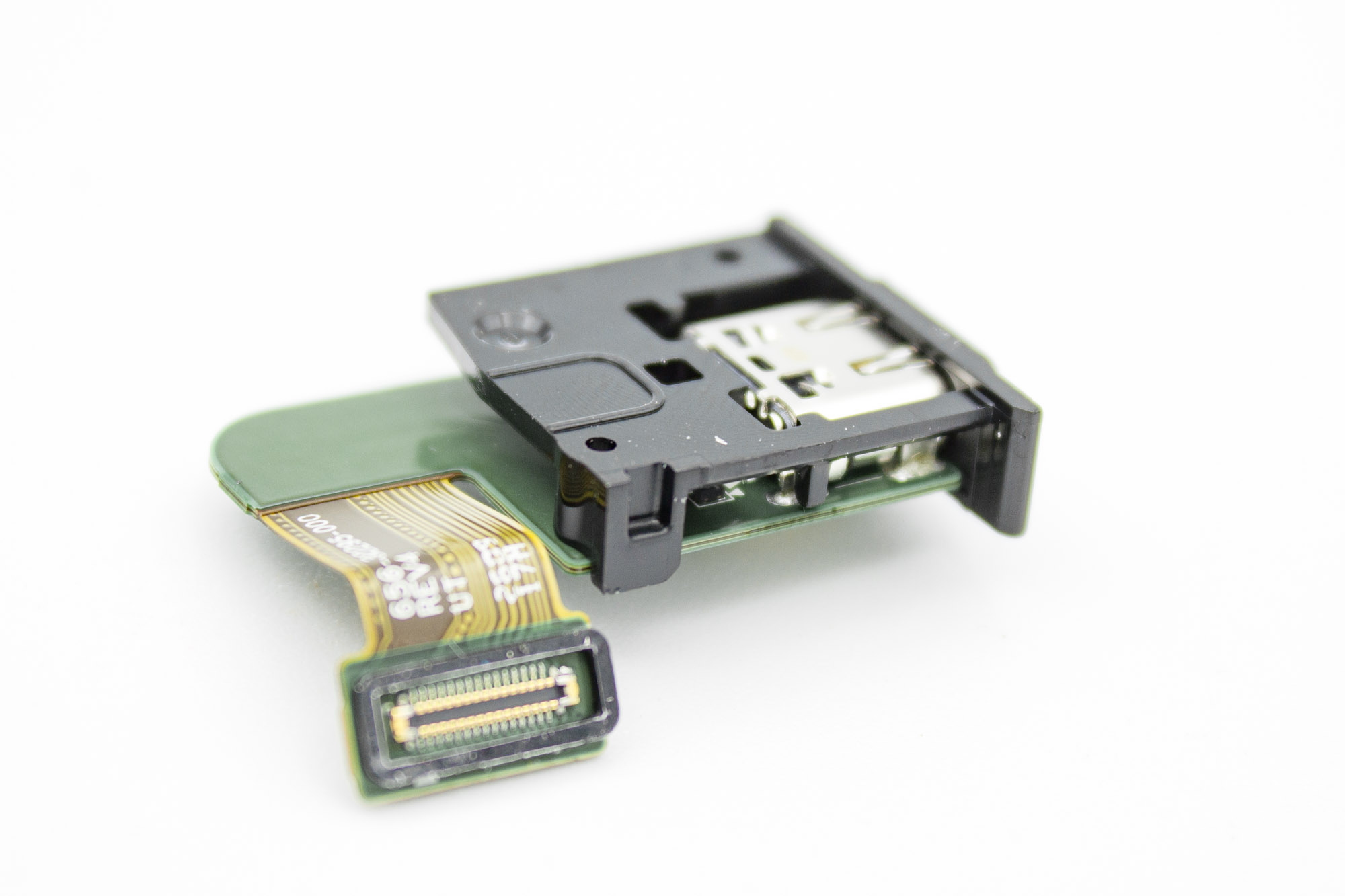
- Lift out the complete USB assembly, including its plastic holder.
Step - Remove the Mainboard
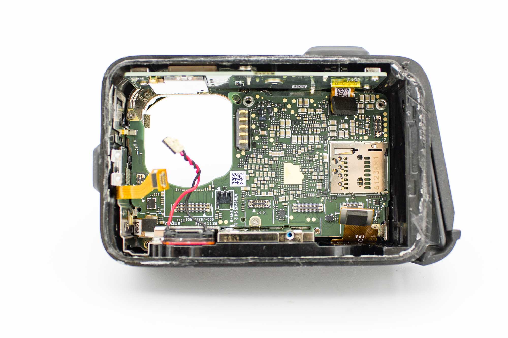
- Remove the three remaining screws securing the mainboard.
- Keep these screws. One will be reused to mount the microphone FPC in the naked case.
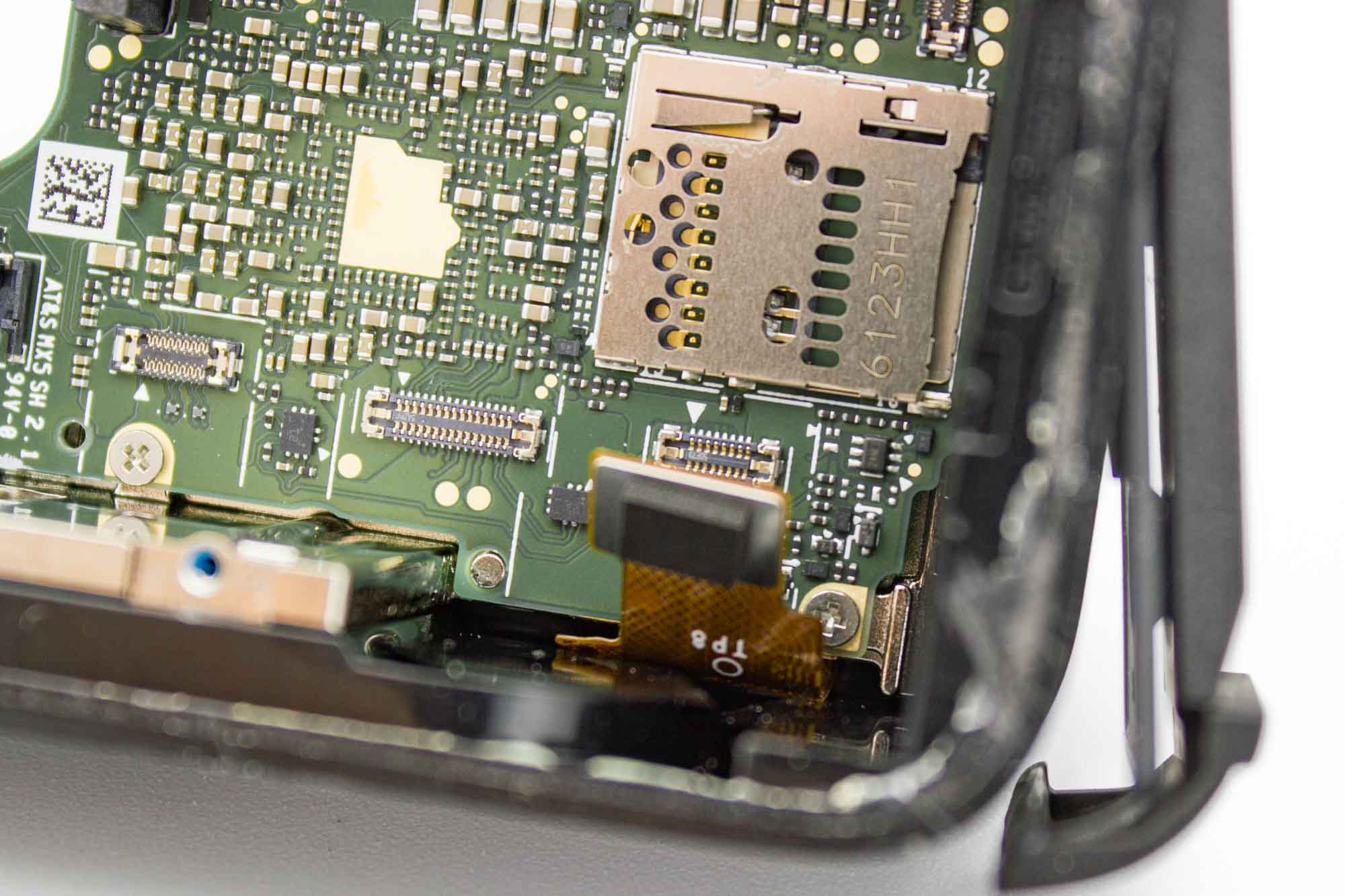
- One screw is hidden behind the front display ribbon connector in the lower right corner.
- Gently move the disconnected cable aside to access it.
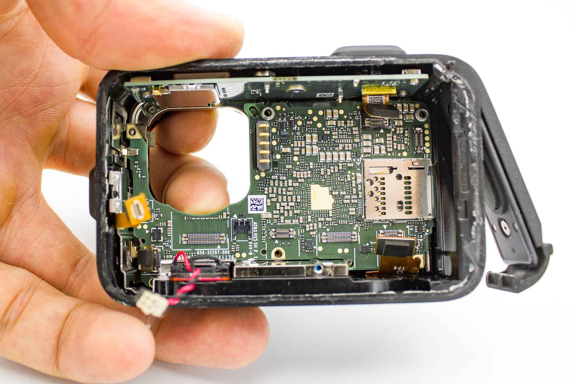
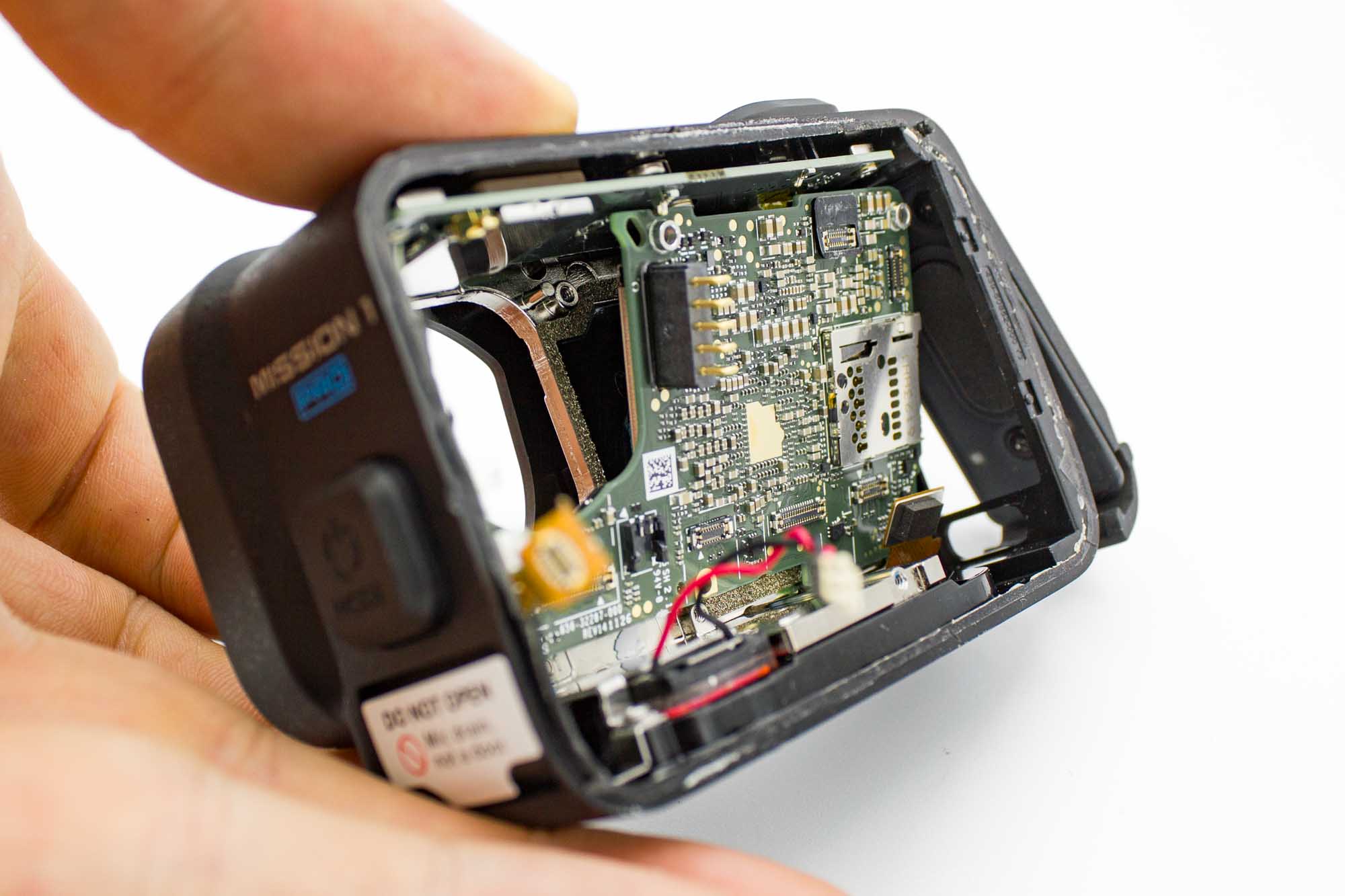
- Check that all cables are disconnected and clear of the board.
- Reach through the lens opening with a finger and gently push the mainboard away from the heatsink.
- The thermal compound may hold the board in place. Apply gentle, even pressure without bending the board.
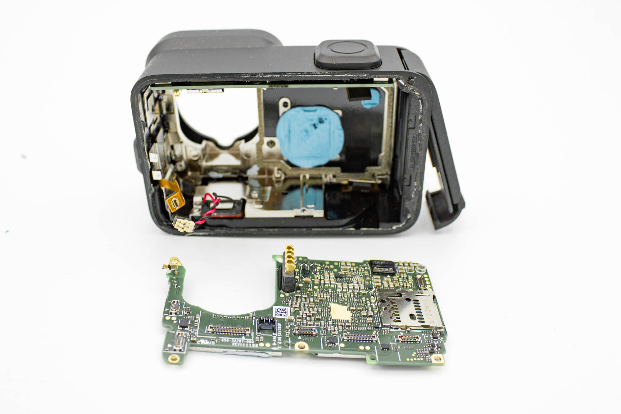
- Lift the mainboard out completely and place it on a clean, non-conductive surface.
Step - Remove the GPS and Bluetooth Board
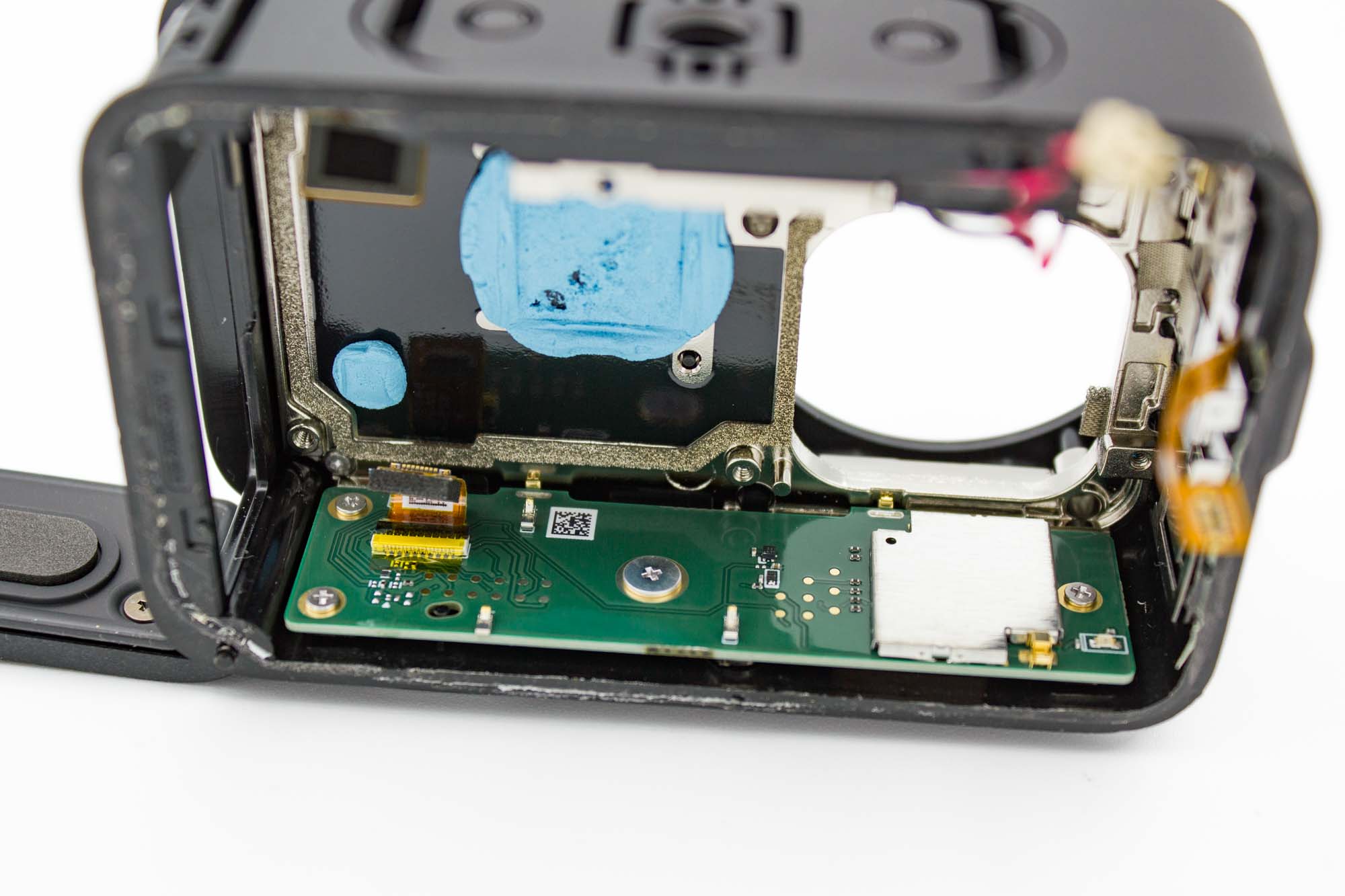
- Remove the four screws securing the GPS and Bluetooth board.
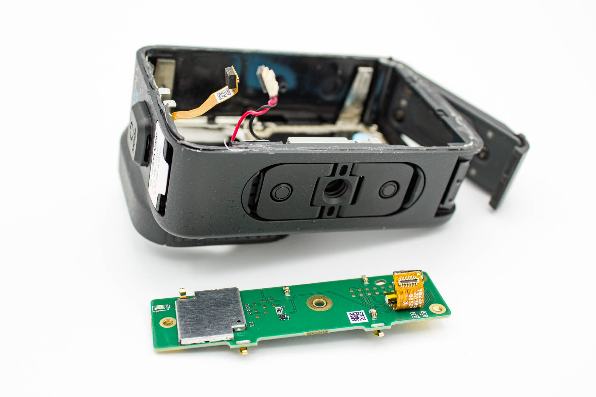
- Lift the board out of the housing and set it aside.
Step - Remove the Bottom GoPro Mount
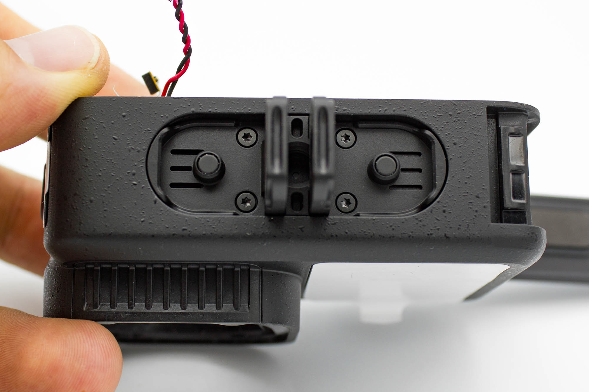
- Unfold the mounting fingers to access the screws.
- Remove the four screws securing the bottom GoPro mount.
- Pull the mount away from the housing.
Step - Remove the Speaker
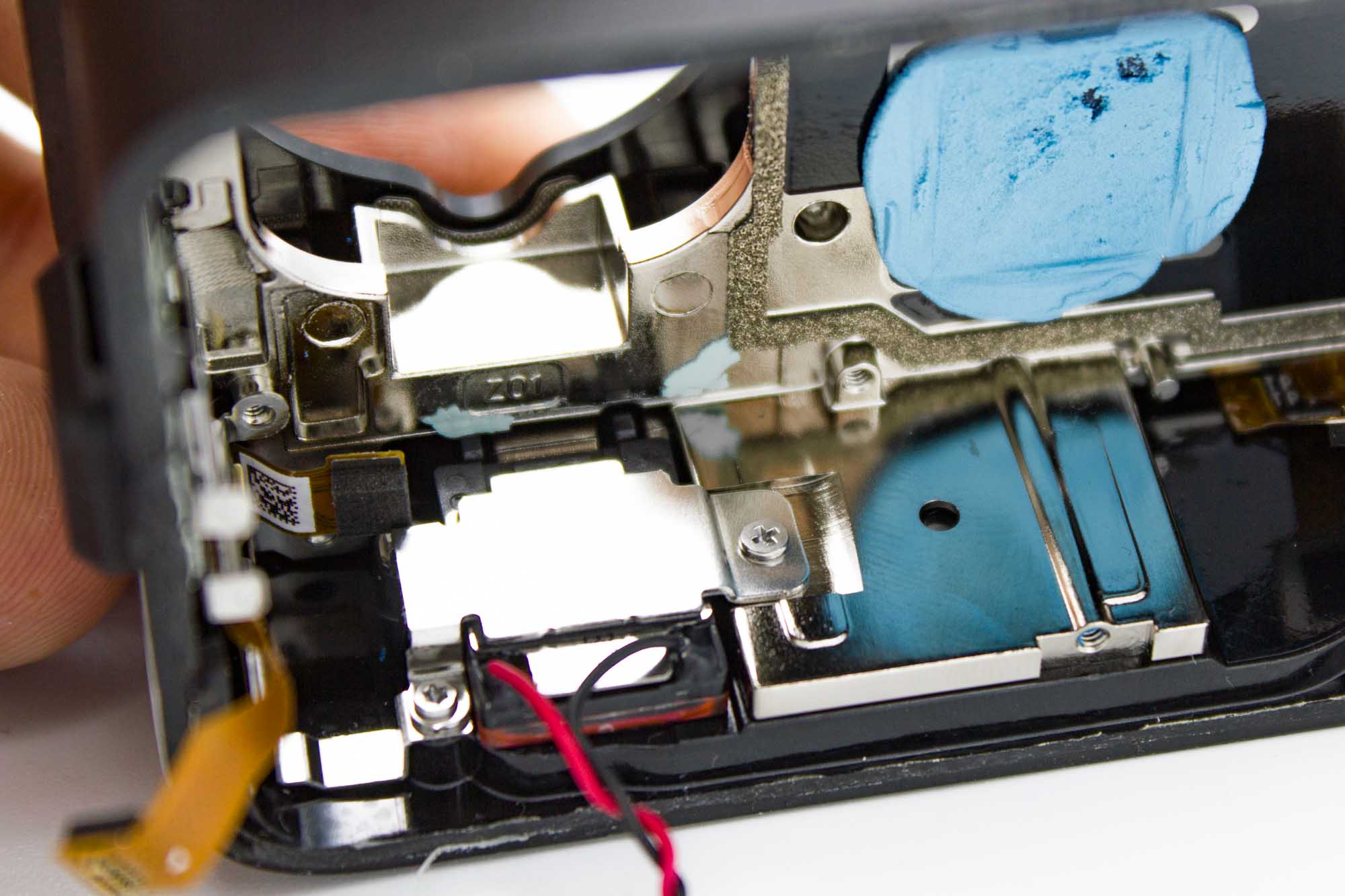
- Remove the screws securing the metal bracket over the speaker.
- The lowest screw is difficult to access.
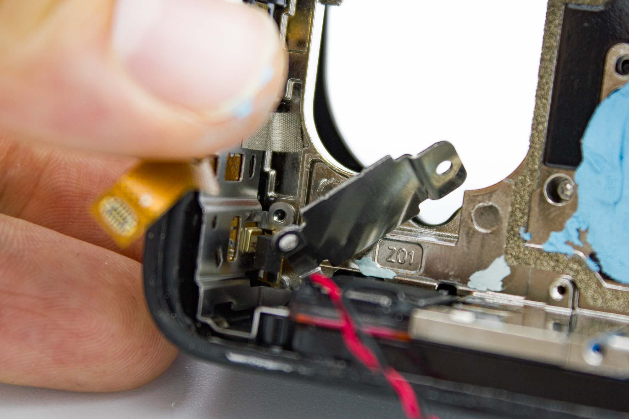
- If you cannot remove the lowest screw, carefully bend the speaker bracket out of the way as shown.
- Keep the bracket clear of nearby ribbon cables.
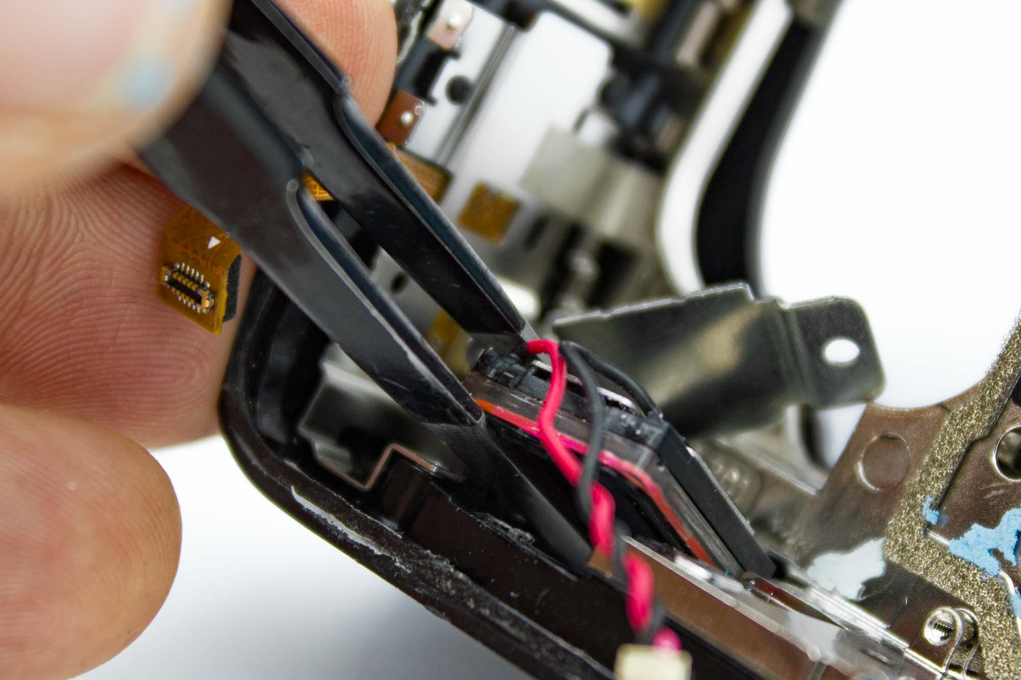
- Insert a thin opening tool between the speaker body and the housing.
- Gently release the speaker and lift it out.
- Do not pull it out by its wires.
Step - Remove the Power Button Assembly
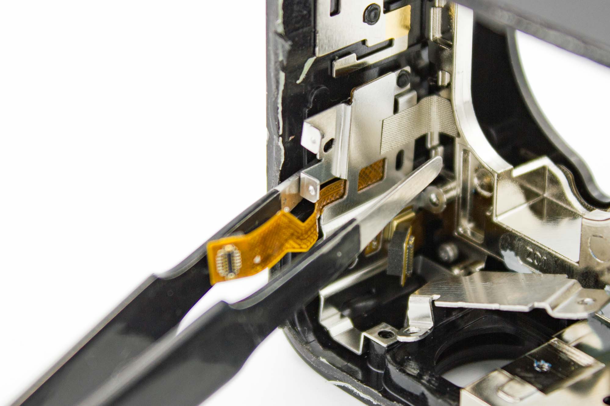
- Insert a thin tool between the power button holder and the housing.
- The holder is secured by melted plastic attachment points.
- Carefully pry the holder away to release these points.
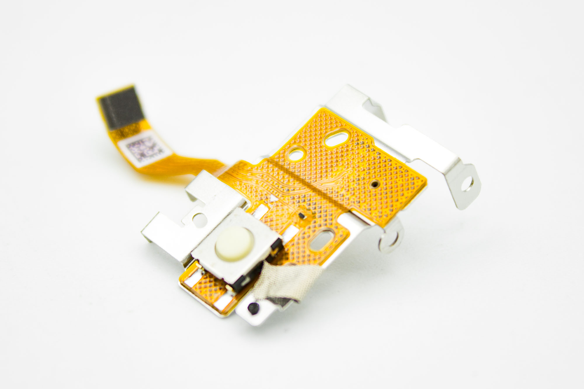
- Remove the power button assembly together with its holder.
- Guide the ribbon cable clear of the housing.
Step - Remove the Heatsink Assembly
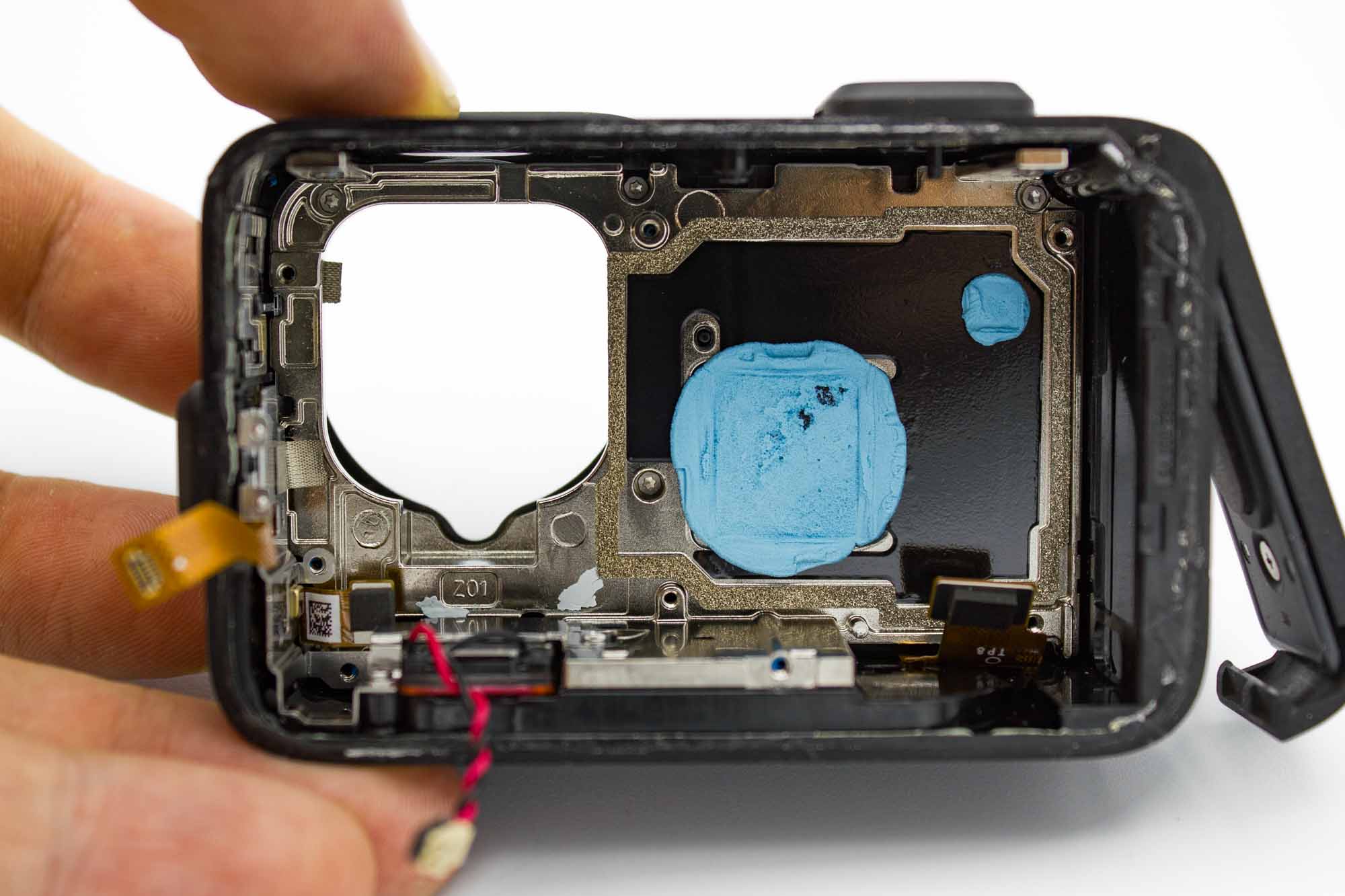
- Remove the five screws securing the heatsink.
- One screw is hidden behind the microphone assembly ribbon connector in the lower left corner.
- Gently move the connector aside to access the screw.
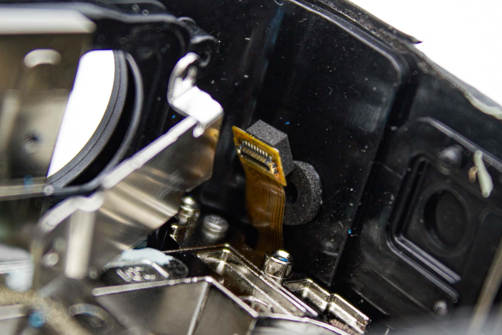
- Carefully lift the heatsink assembly out of the housing.
- The front display and microphone FPC are still attached to it.
- Guide both ribbon connectors past the housing so they do not catch or tear.
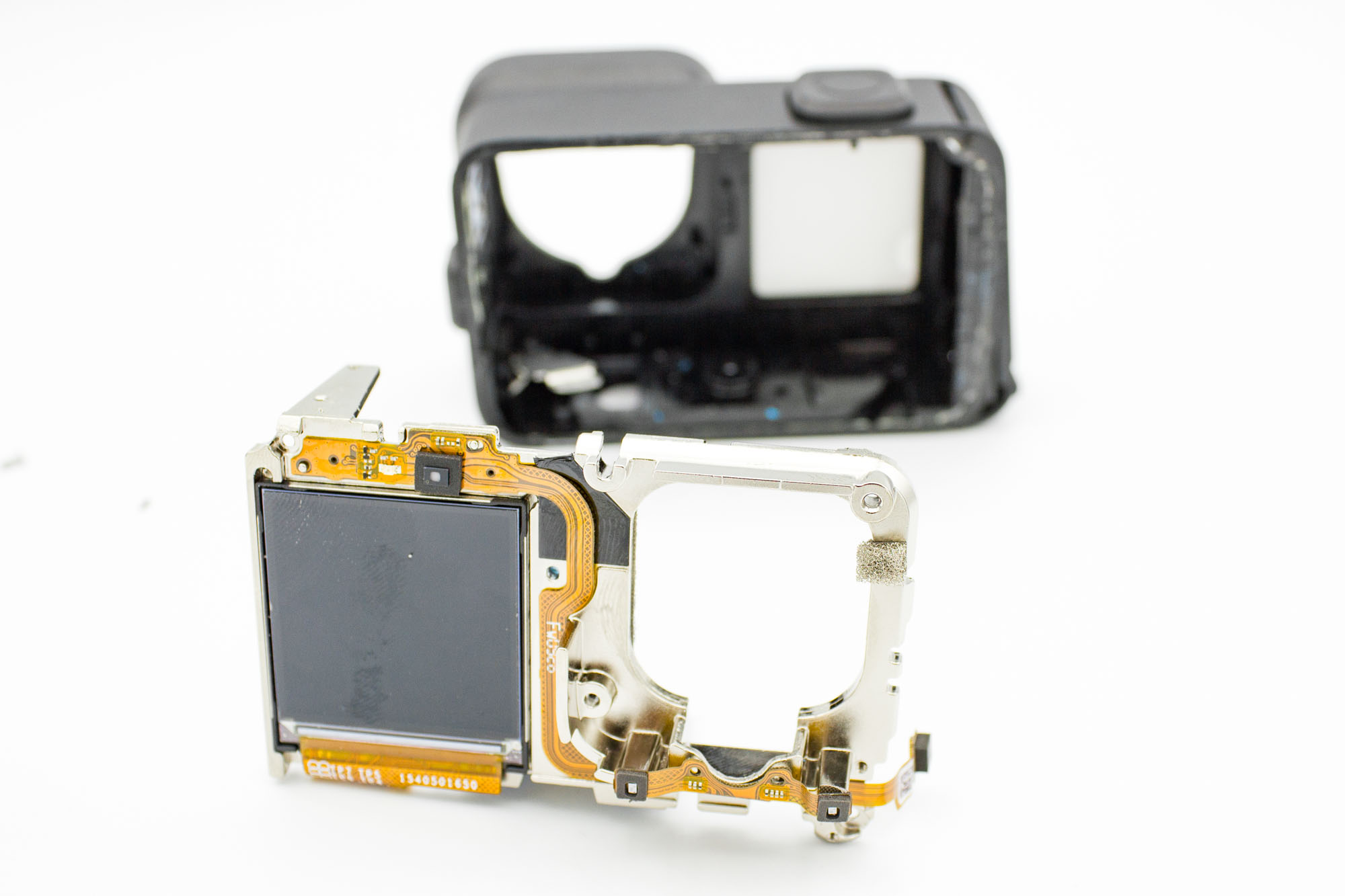
- Remove the complete heatsink assembly and place it on your work surface.
Step - Remove the Front Display
The front display is fragile. Do not bend it or force it away from the heatsink.
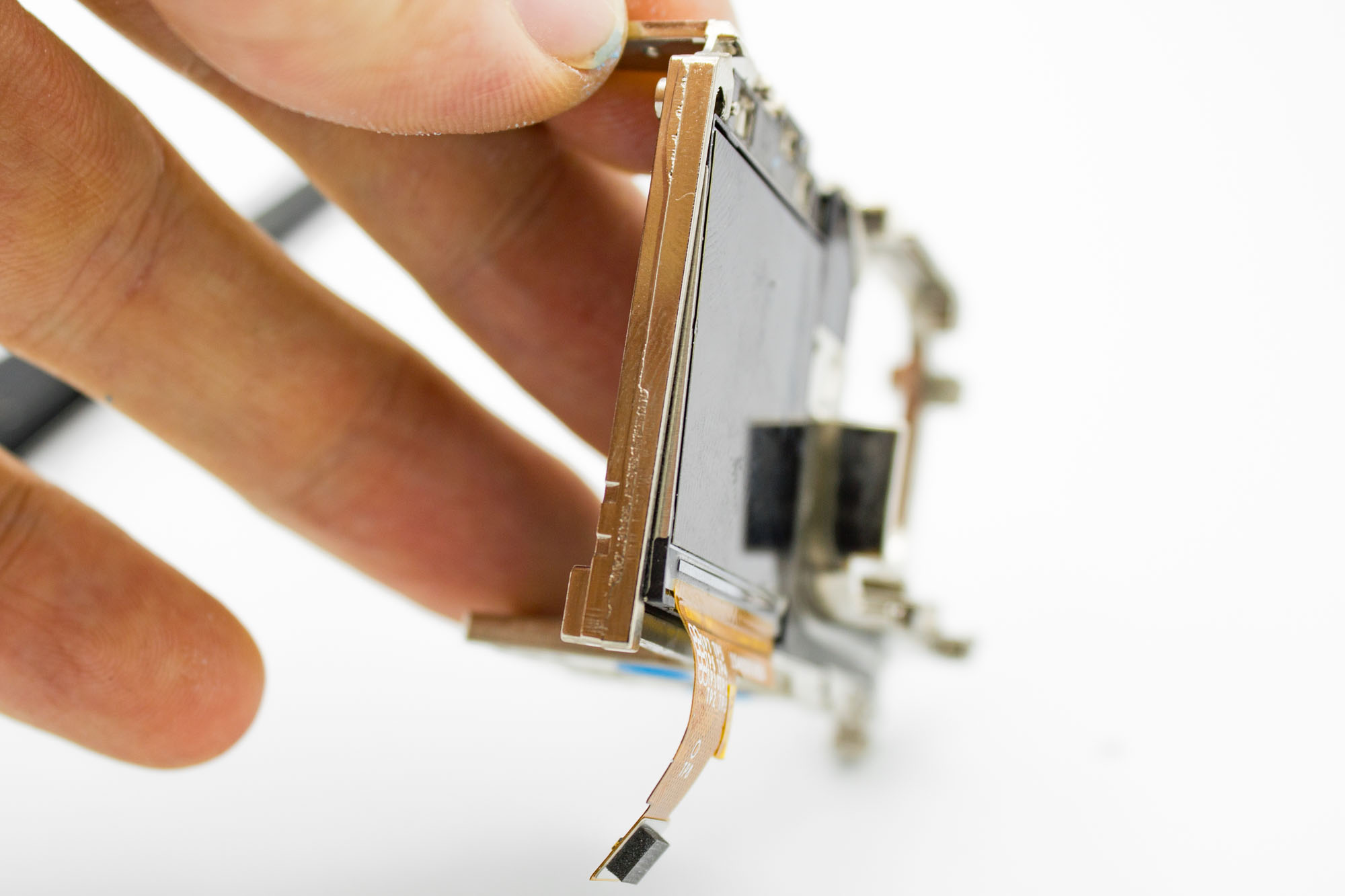
- Gently heat the heatsink behind the front display to soften the adhesive.
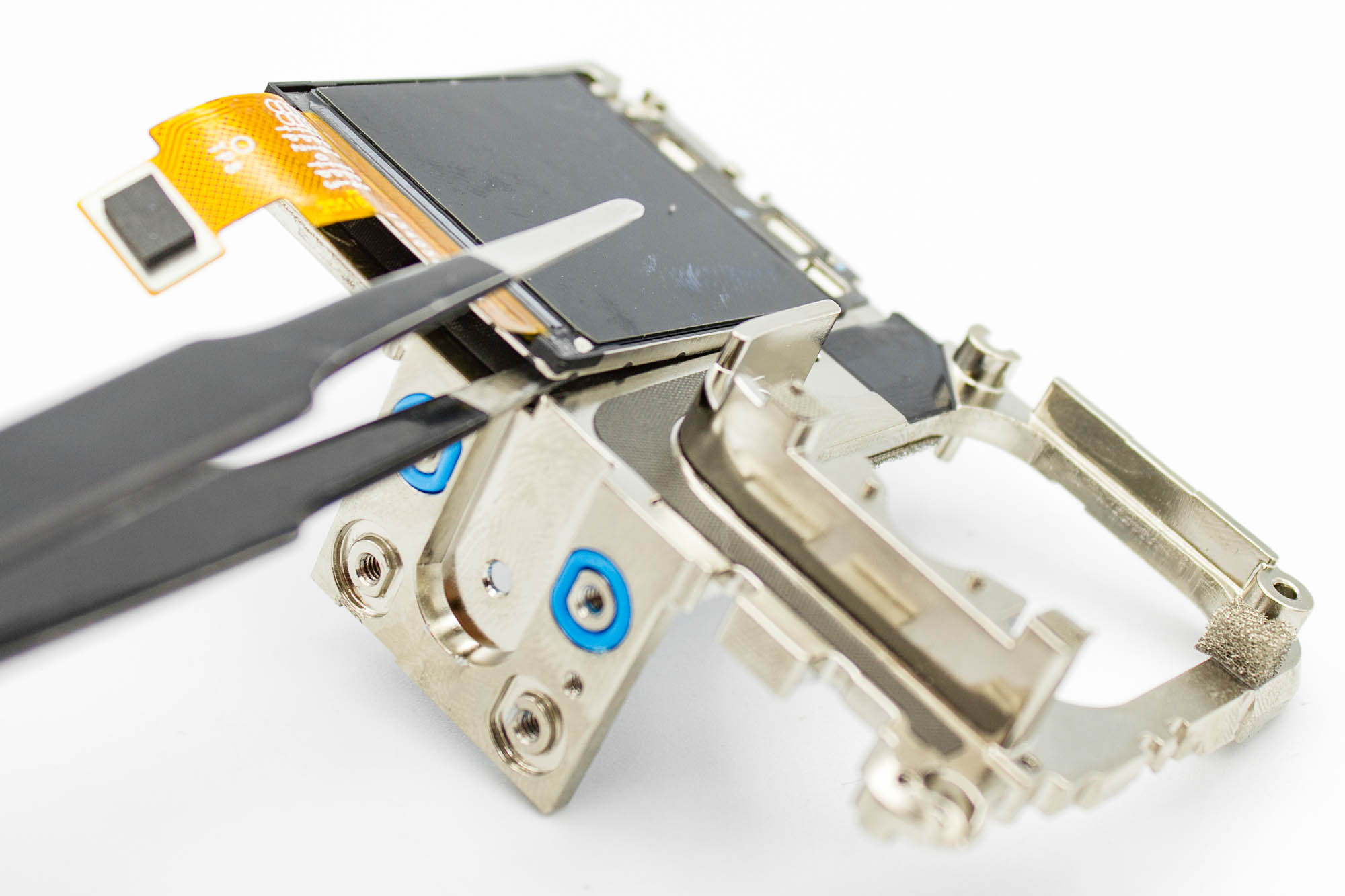
- Carefully slide a thin opening tool between the heatsink and the back of the display.
- Work slowly across the bonded area, keeping the display as flat as possible.
- If the adhesive does not release, apply a little more heat and continue gradually.
- Remove the display without pulling on its ribbon cable.
Step - Remove the Microphone FPC
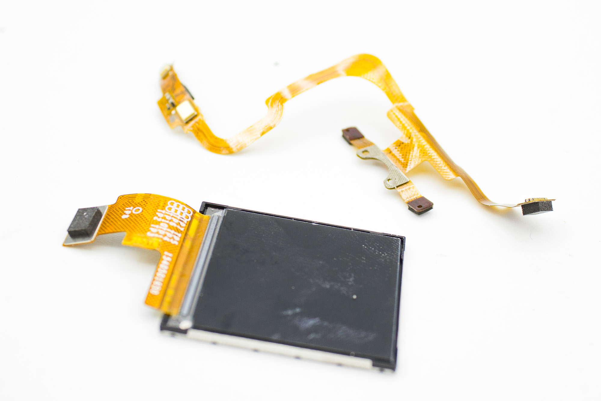
- Gently heat the heatsink behind the microphone FPC to soften its adhesive.
- Carefully peel the FPC away, supporting it close to the area being released.
- Keep the ribbon cable, microphones, and connector intact.
- The front display and microphone FPC should now be separated from the heatsink as shown.
Step - Clean the Mainboard
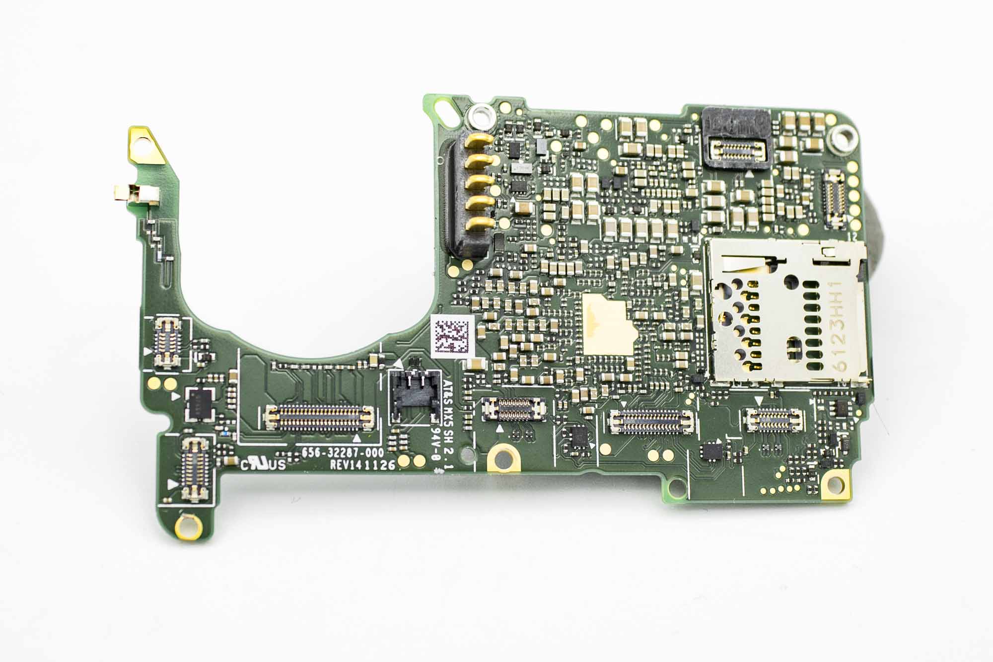
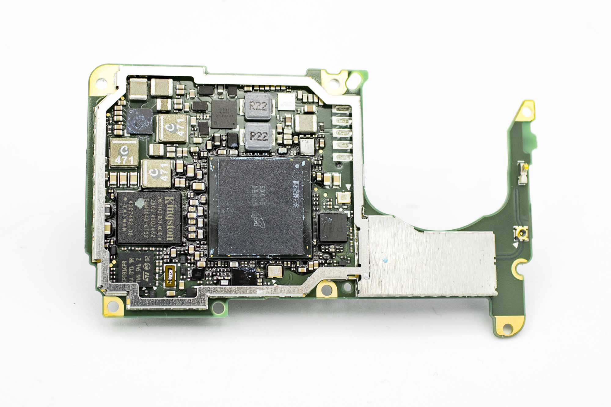
- Carefully remove the remaining thermal compound from the mainboard.
- Avoid scraping or lifting any of the small components.
- Keep residue out of the connectors and microSD card slot.
Step - Separate the Lens from Its Original Housing
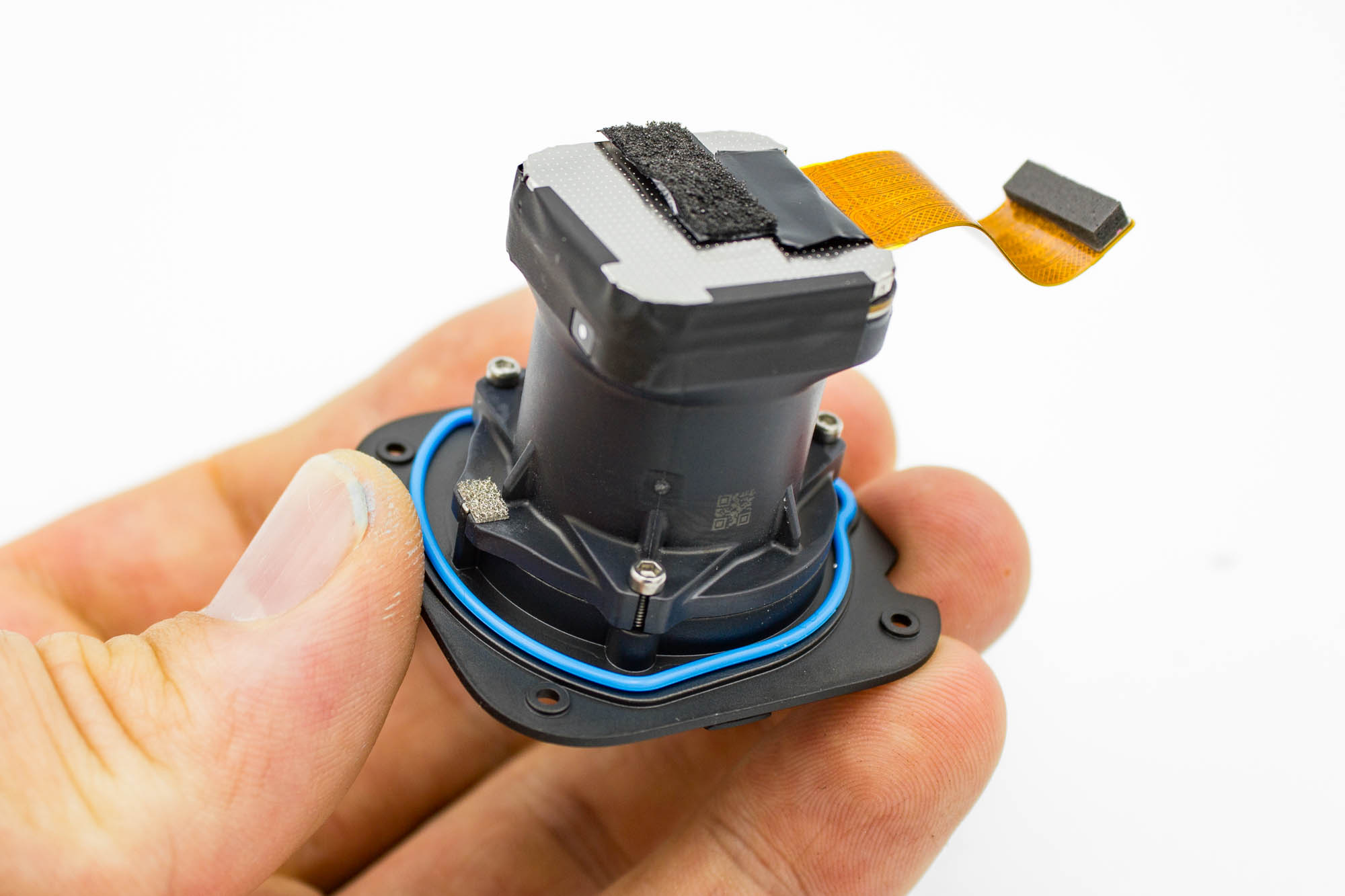
- Remove the three screws around the lens assembly that secure it to its original housing.
- Separate the complete lens and sensor assembly from the housing.
- Do not disturb the sensor PCB or pull on its ribbon cable.
Disassembly is now complete. Continue with the preparation and assembly of the naked case.
Assembly Steps
Step - Install the Light Pipe
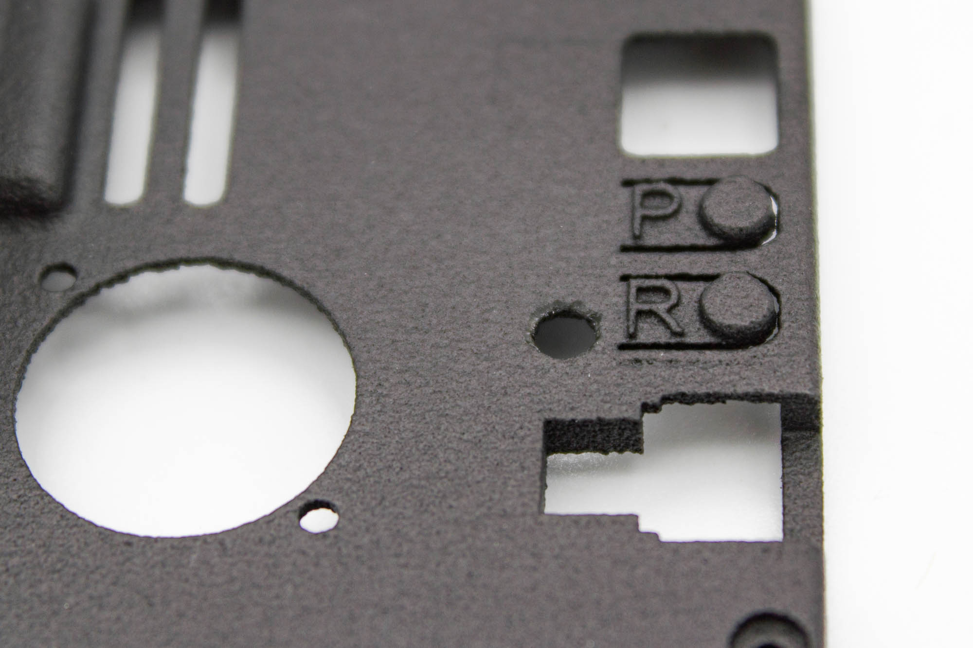
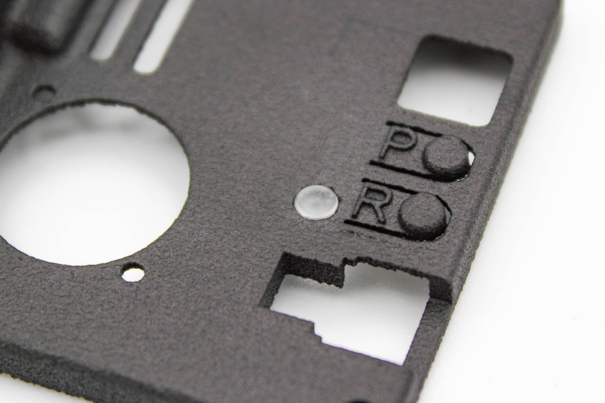
- Insert the light pipe into the round hole next to the REC button on the back case.
- If the fit is too tight, carefully widen the hole slightly.
- Remove only enough material for the light pipe to fit securely.
Step - Install the Threaded Inserts
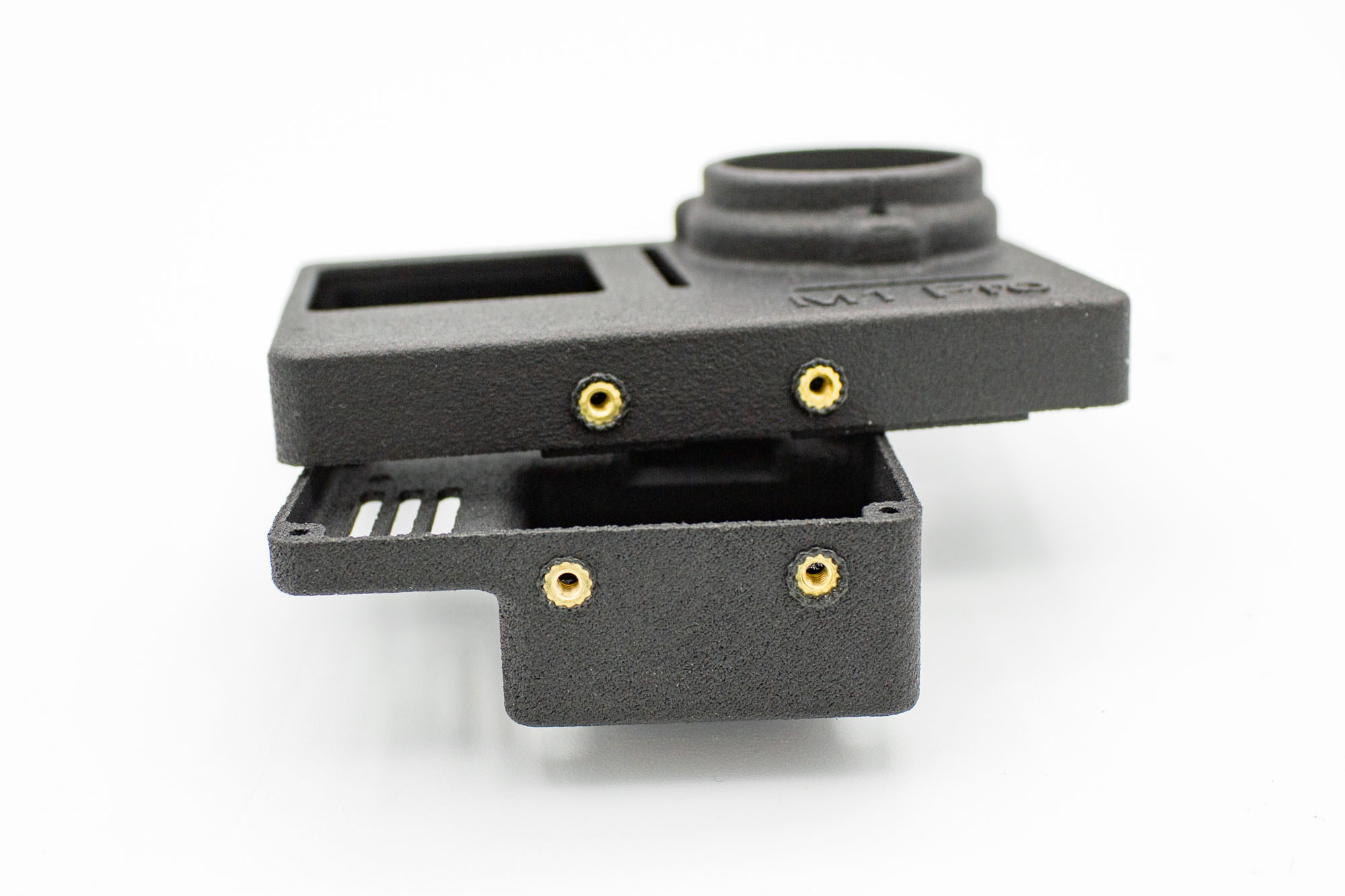
- Use a soldering iron to heat and install the four threaded inserts: two in the front case and two in the back case.
- Press each insert in slowly and keep it straight.
- Let the inserts and surrounding plastic cool before continuing.
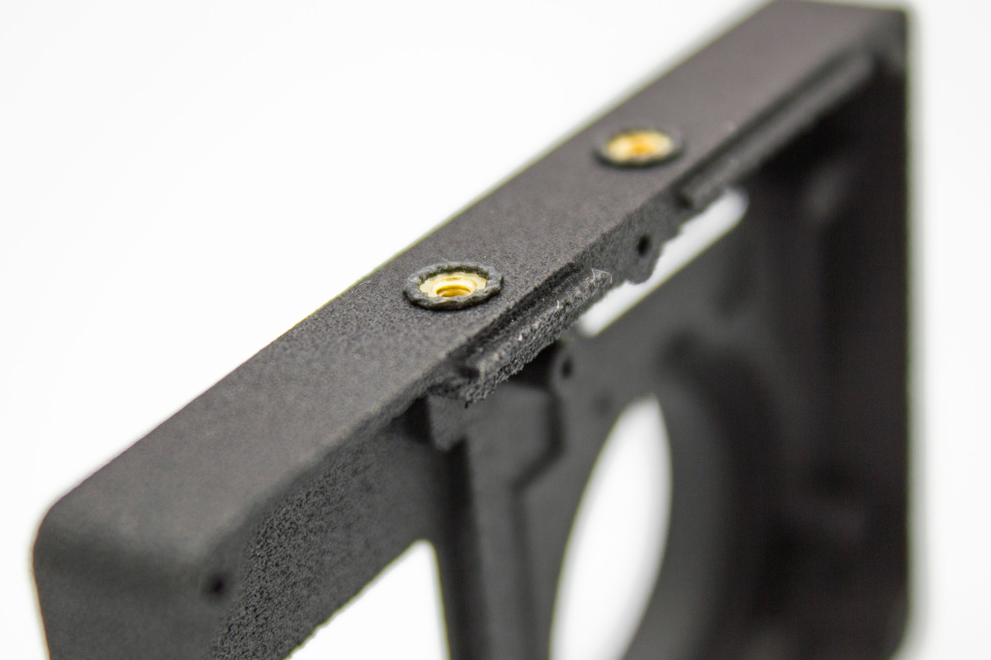
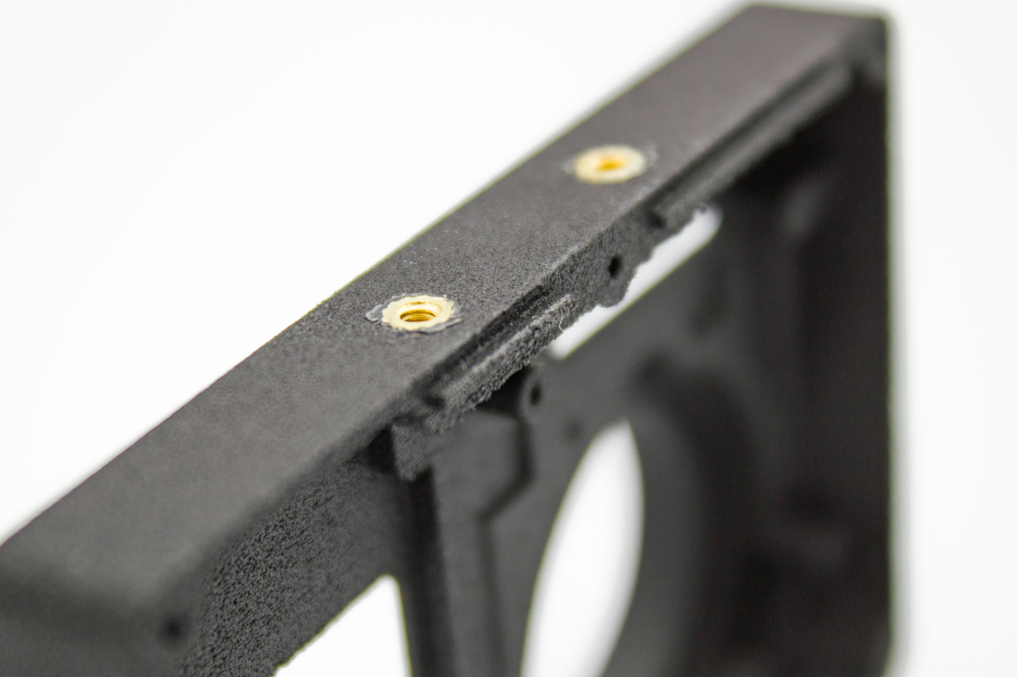
- Carefully trim away the raised plastic around each insert.
- Leave the surrounding surface flush, as shown in the second picture.
- Remove all loose plastic from both case halves before installing the electronics.
Step - Prepare the Microphone FPC
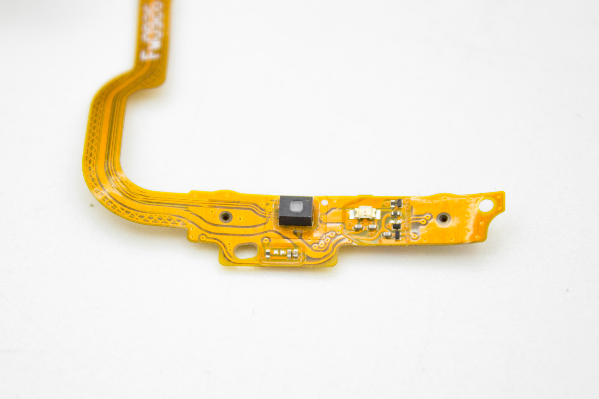
- Locate the raised black light sensor cover shown in the picture.
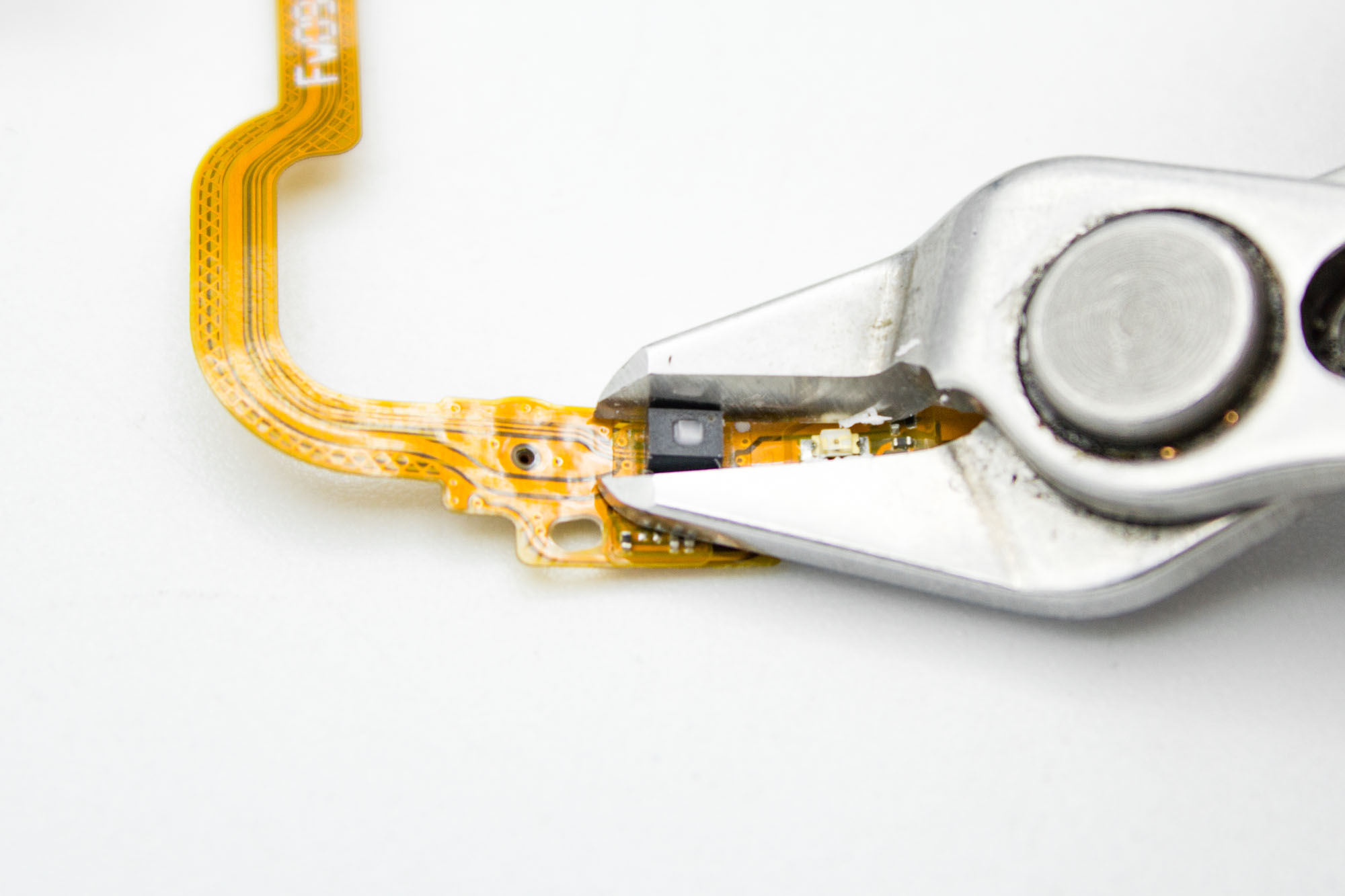
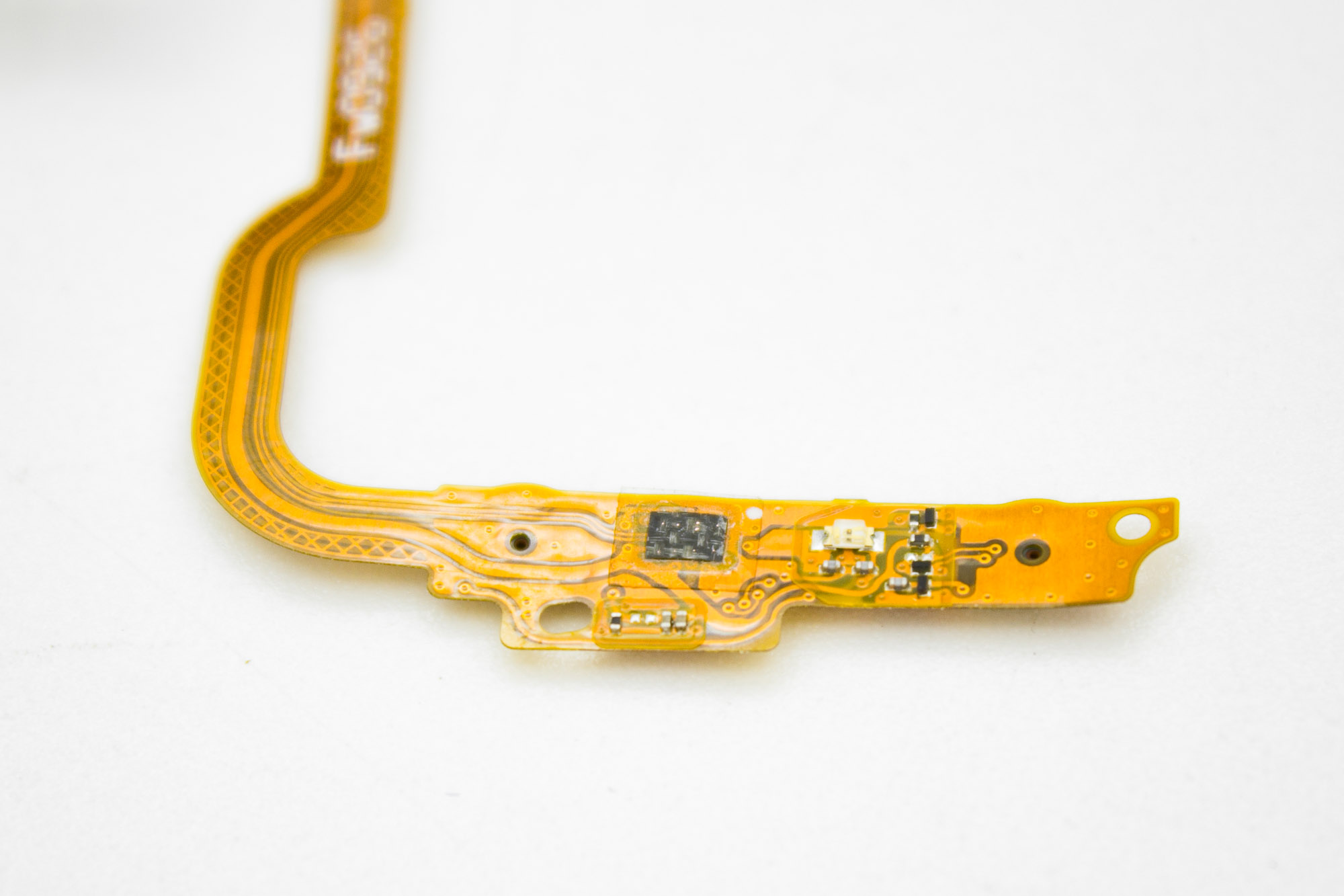
- Carefully trim away the raised cover with fine flush cutters so the FPC can sit flat in the new housing.
- Match the finished result shown in the picture.
- Do not cut through the FPC or damage the surrounding components and traces.
Step - Install the Microphone FPC
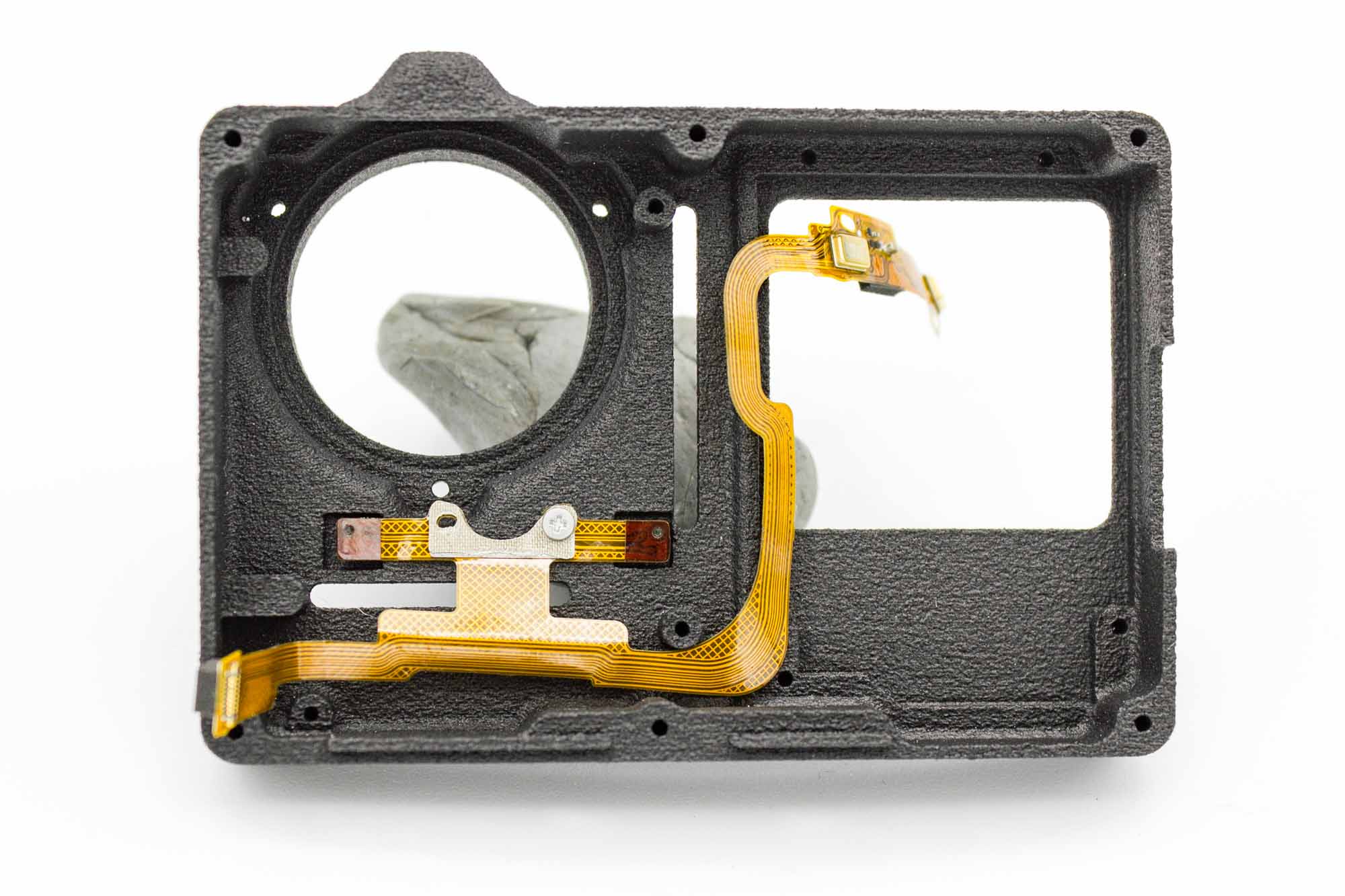
- Place the microphone FPC into the front case.
- Route it along the recesses as shown.
- Secure the small metal mounting bracket with one original mainboard screw saved during disassembly.
- Leave the upper section free so it can be positioned over the display mount in the next step.
- Make sure the FPC lies flat and is not twisted or pinched.
Step - Install the Front Display
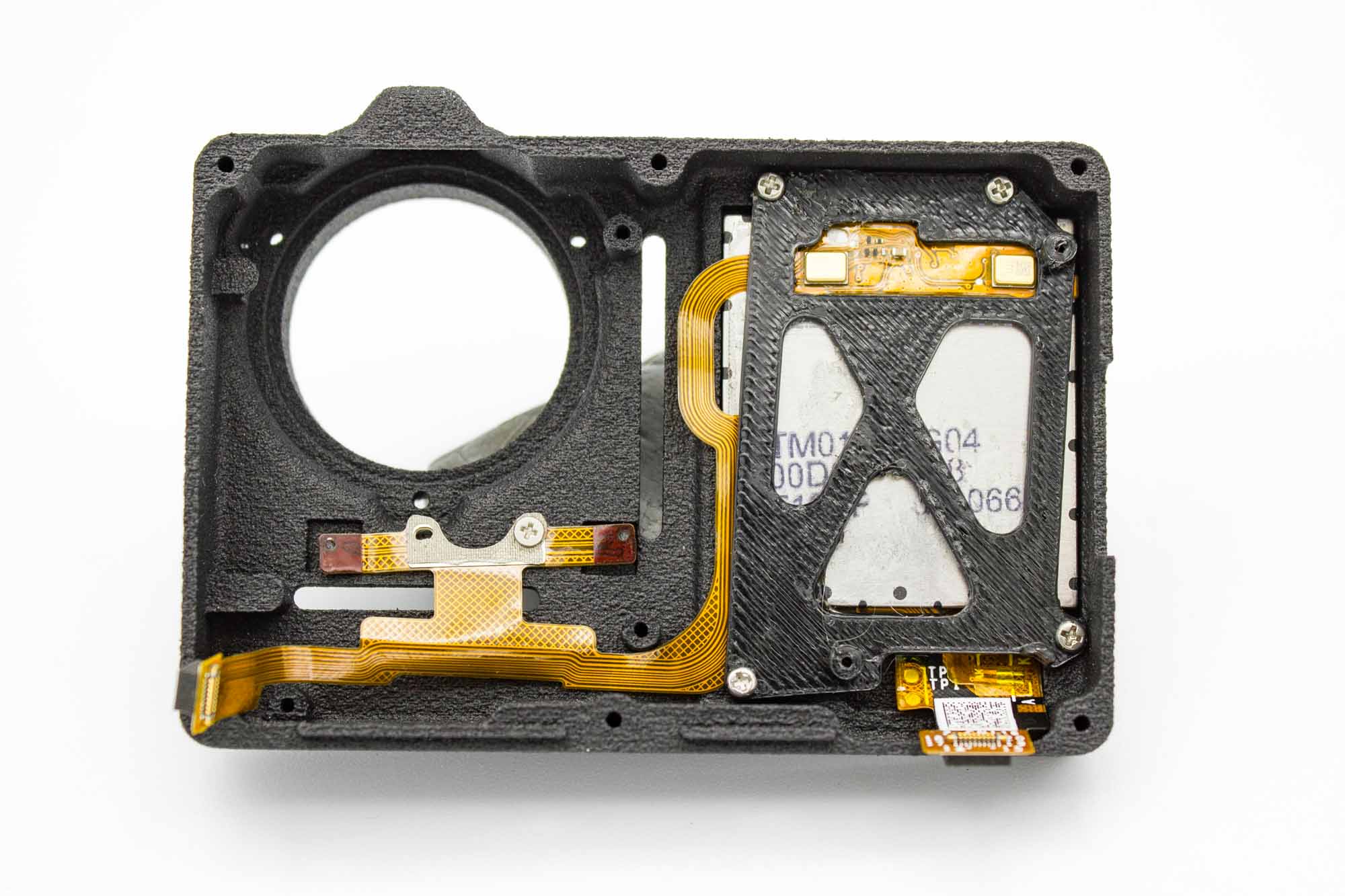
- Place the front display into the front case with the screen facing outwards.
- Check its orientation against the picture.
- Position the 3D printed display mount over the back of the display.
- Secure the mount with four M1.4 x 3mm screws.
- Position the upper microphone FPC section in the opening of the display mount as shown.
- Keep the display ribbon cable clear of the mount and screws.
- Tighten the screws gently and evenly. Do not overtighten them.
Step - Insulate the Microphone Housings
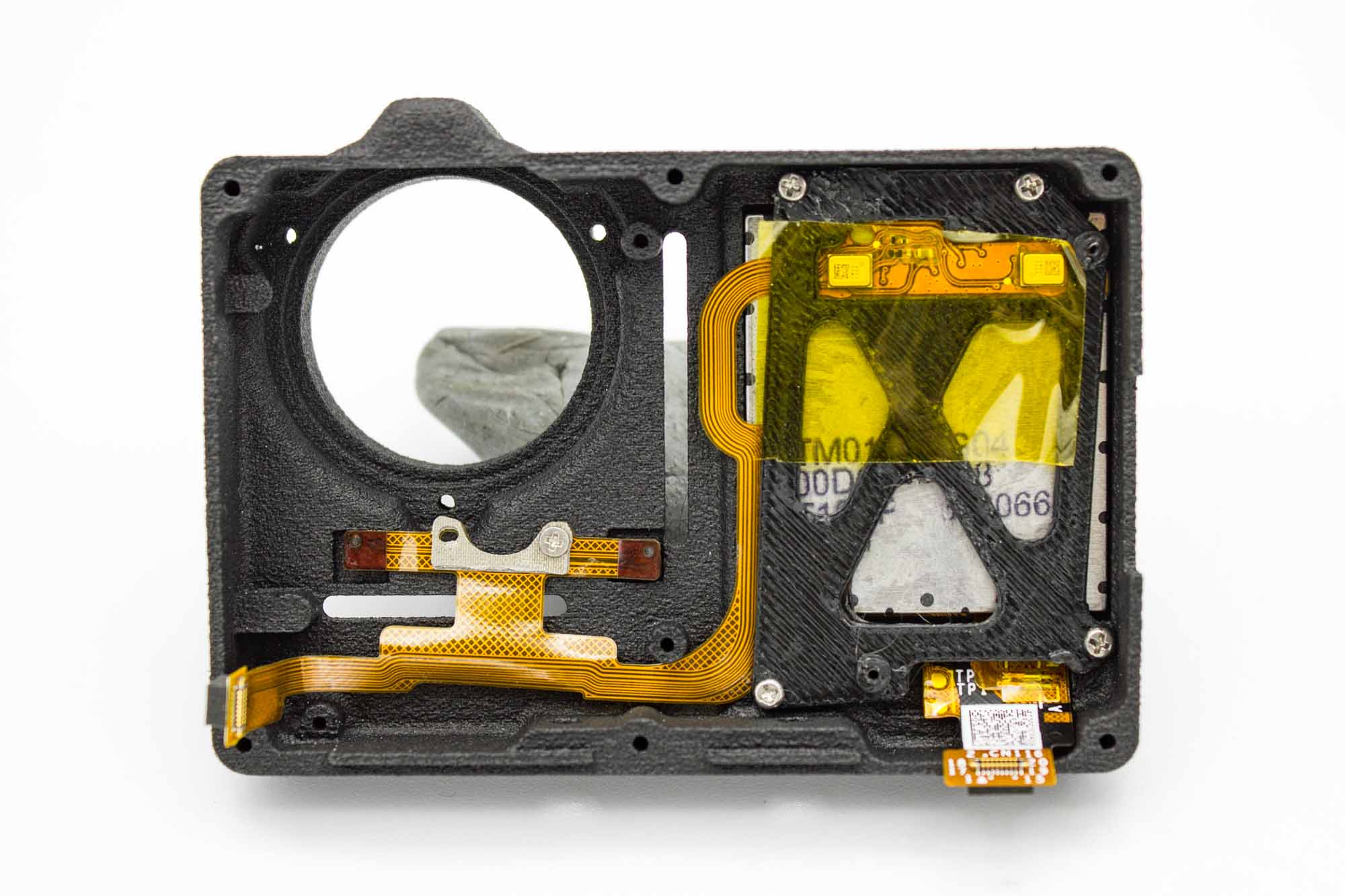
- Apply Kapton tape or suitable electrical insulating tape over the exposed metal microphone housings as shown.
- This prevents contact between the microphone housings and the mainboard.
- Make sure the tape stays in place before installing the mainboard.
Step - Remove the Lens Rubber Ring
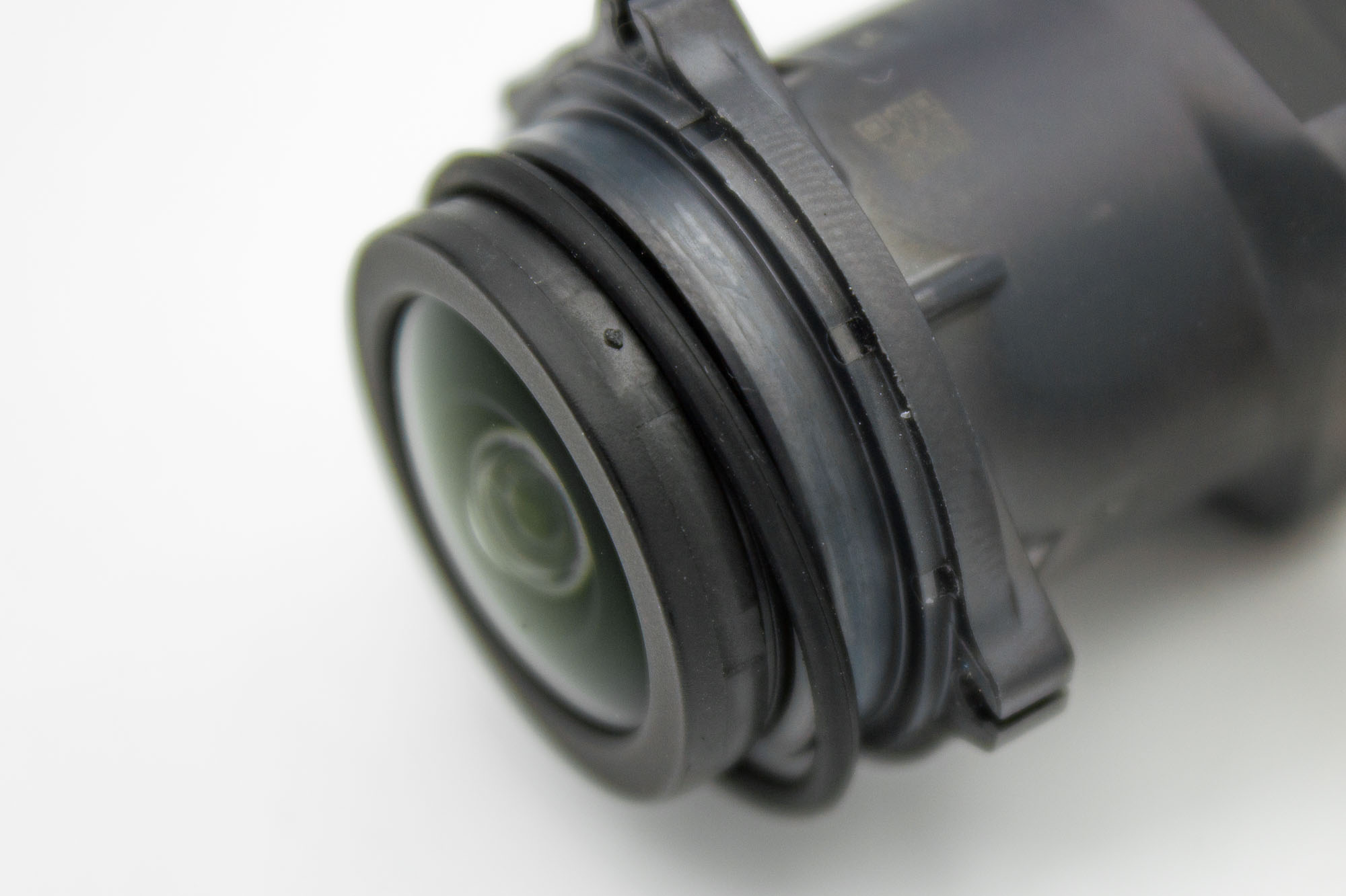
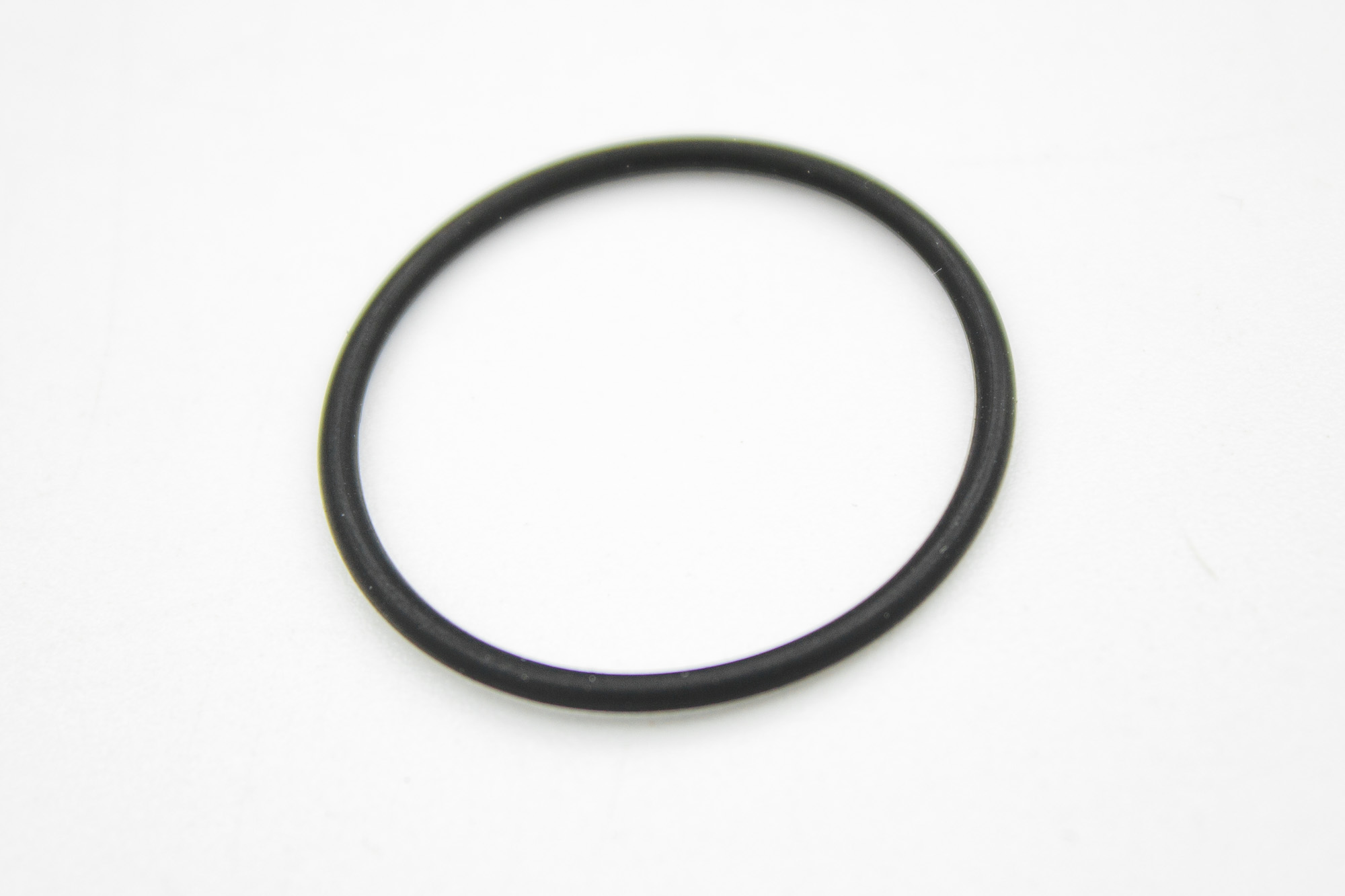
- Remove the rubber ring around the front of the lens assembly.
- Avoid touching or scratching the lens glass.
Step - Install the Lens Assembly
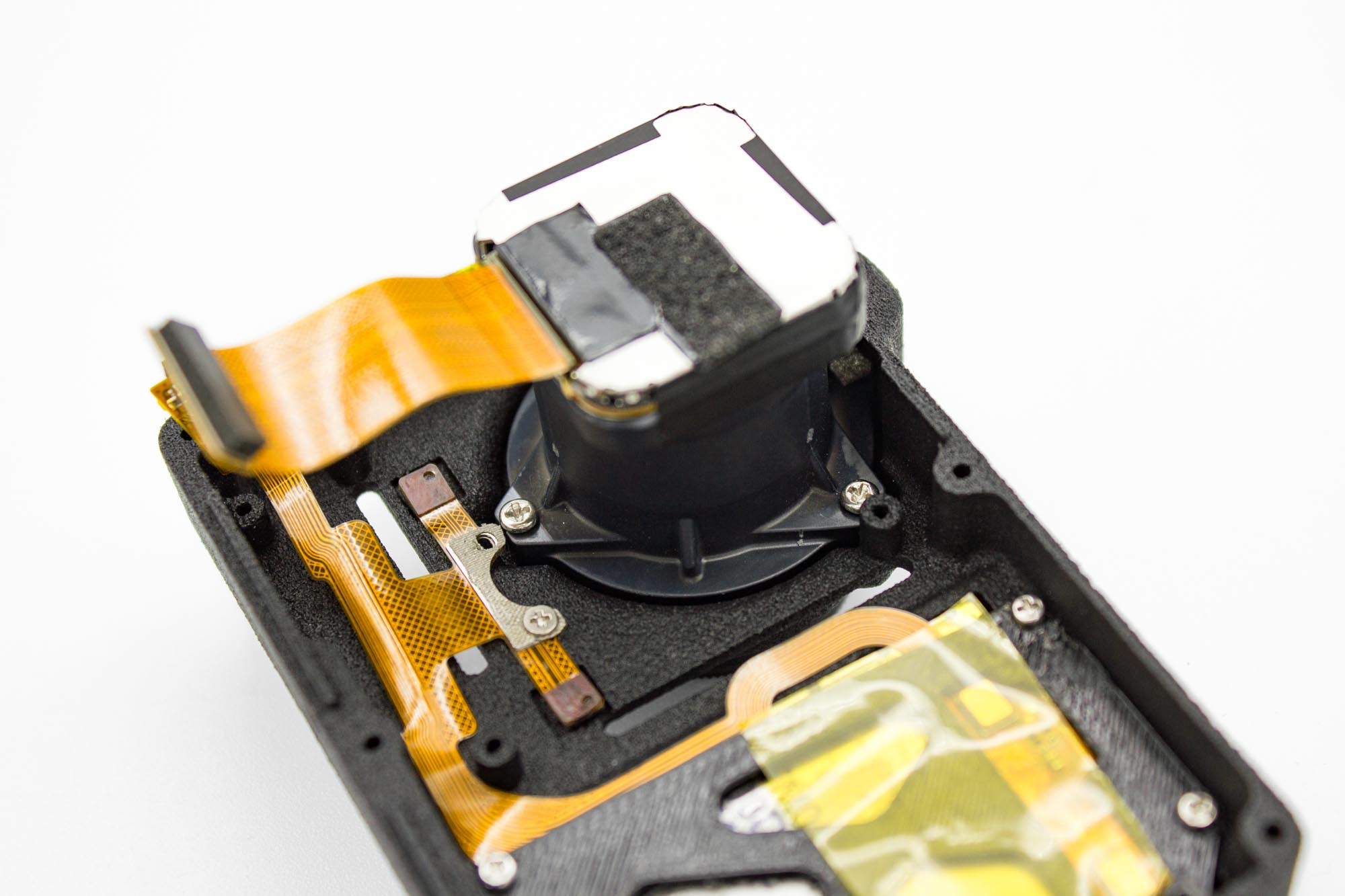
- Place the lens assembly into the front case.
- Match the orientation shown, with the sensor ribbon cable accessible for connection to the mainboard.
- Secure the lens assembly with three M1.6 x 6mm screws.
- Tighten the screws evenly without overtightening.
Step - Prepare the Clear UV Filter
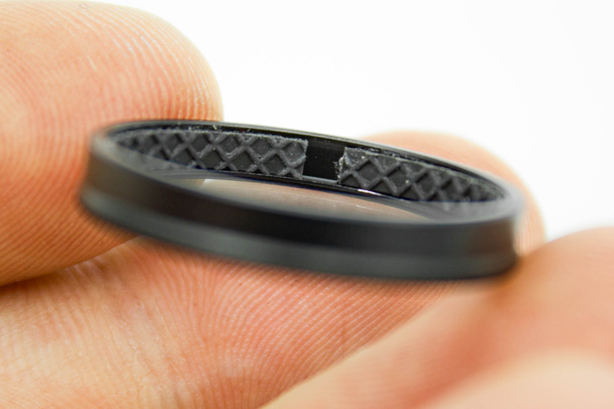
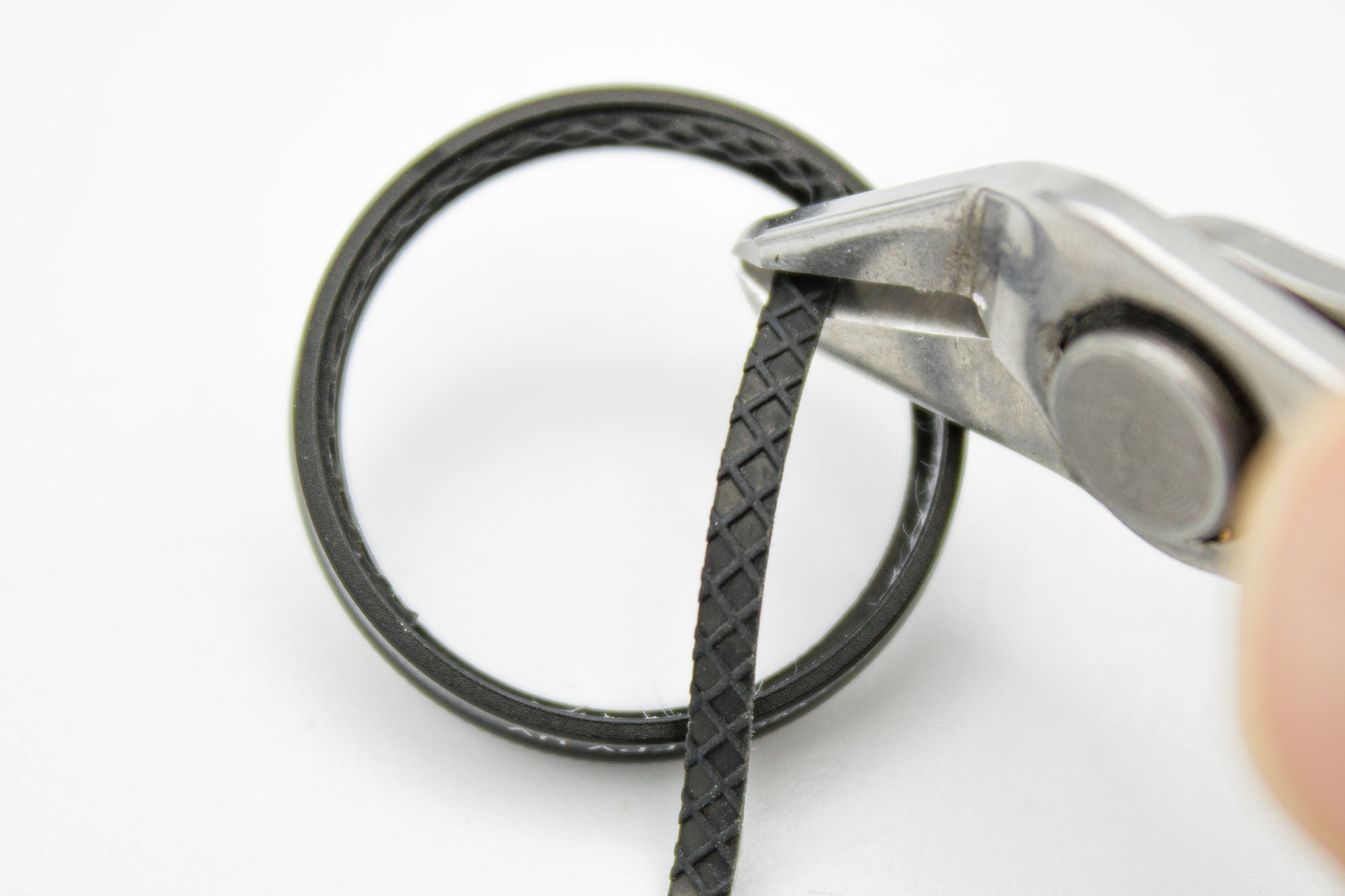
- Carefully lift part of the rubber retaining ring out of the clear UV filter.
- Cut away approximately one third of the ring's circumference.
- Seat the remaining rubber back inside the filter.
- Keep the cutting tool clear of the filter glass and remove any loose debris.
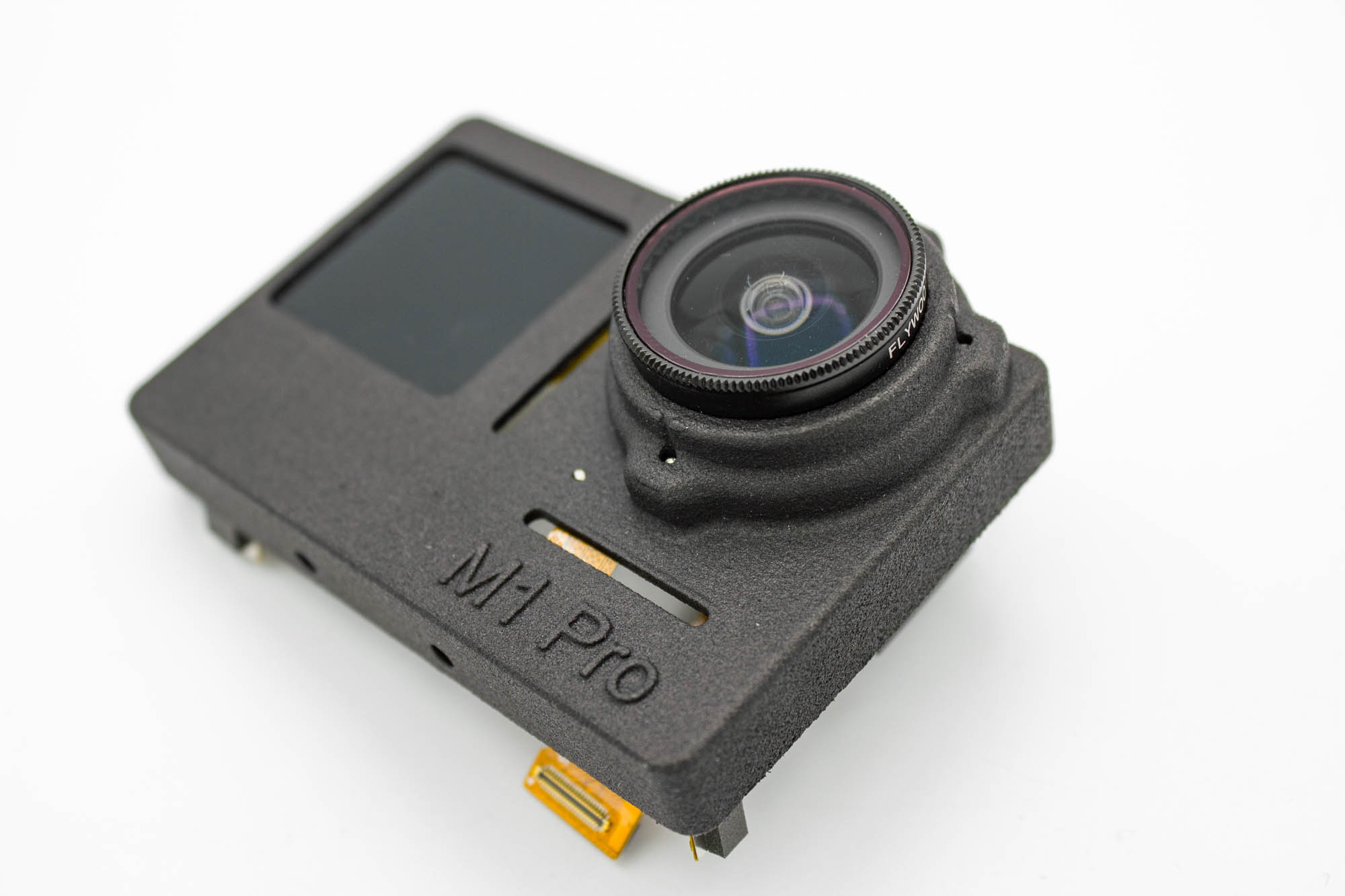
- Fit the clear UV filter onto the lens.
- Leave it fitted to protect the lens during the remaining assembly steps.
Step - Connect the Custom FPC
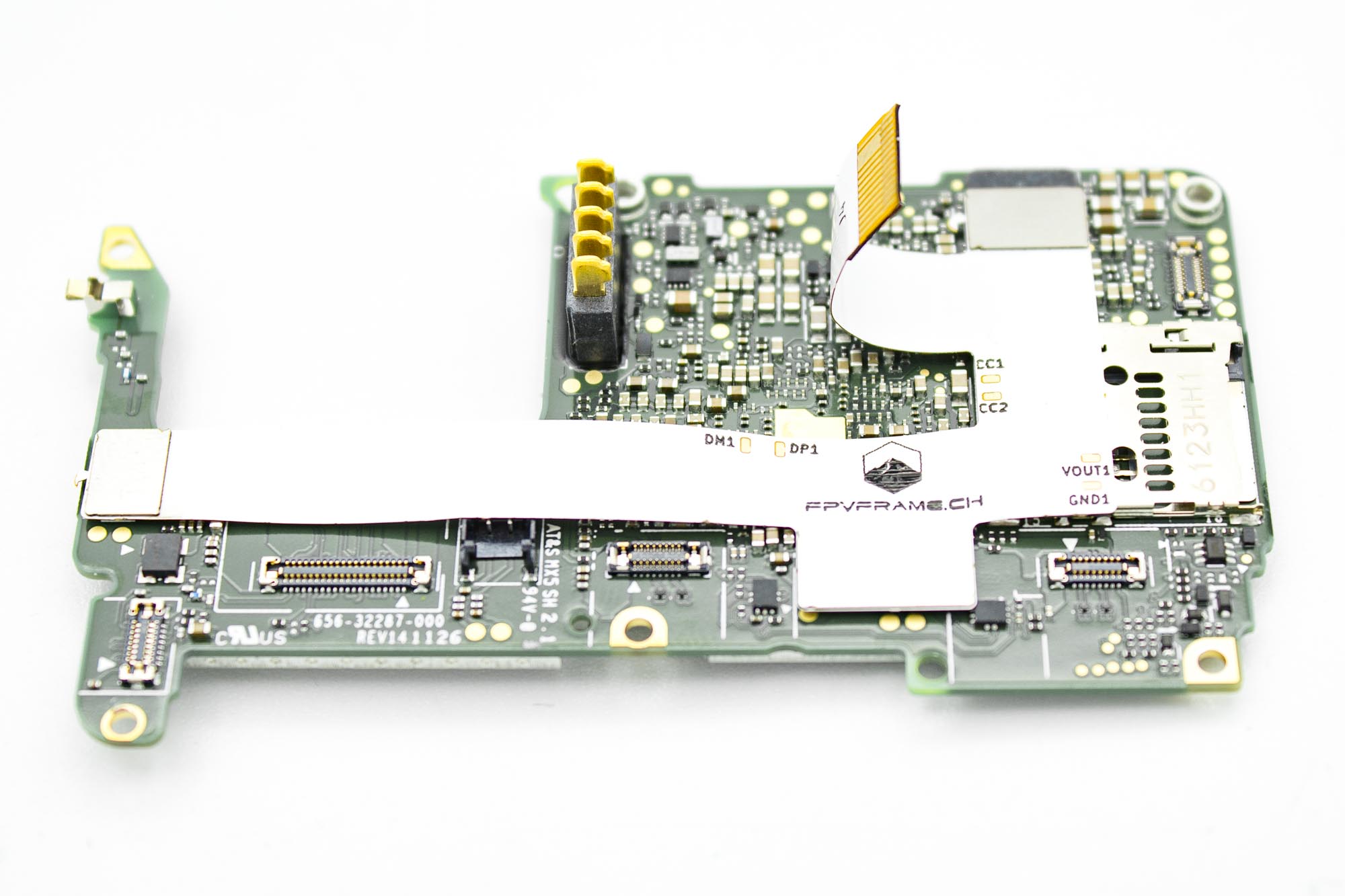
- Connect the FPVFrame.ch custom white FPC to the GoPro mainboard as shown.
- Carefully align each connector before pressing it into place.
- Do not force a connector if it does not sit correctly. Lift it off, check the alignment, and try again.
- Leave the free end accessible for connection to the BEC.
Step - Install the Mainboard
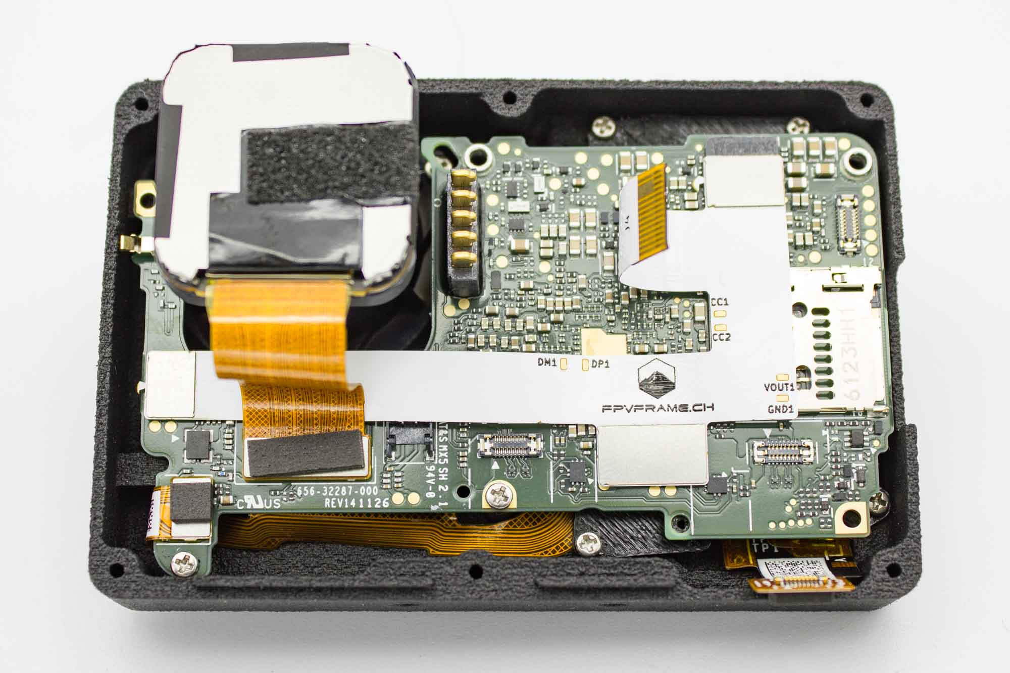
- Lower the mainboard into the front case.
- Make sure the sensor, front display, and microphone ribbon cables remain accessible.
- Check that no cables are trapped underneath the board.
- Secure the mainboard with two M1.4 x 4mm screws at the lower left and lower middle mounting positions, viewed as shown.
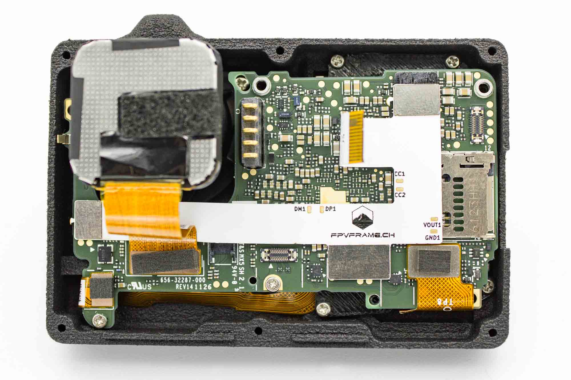
- Connect the sensor, front display, and microphone FPC connectors to the mainboard.
- Align each connector carefully before applying pressure.
- Check that all connectors sit flat and are fully seated.
Step - Install the BEC Holder
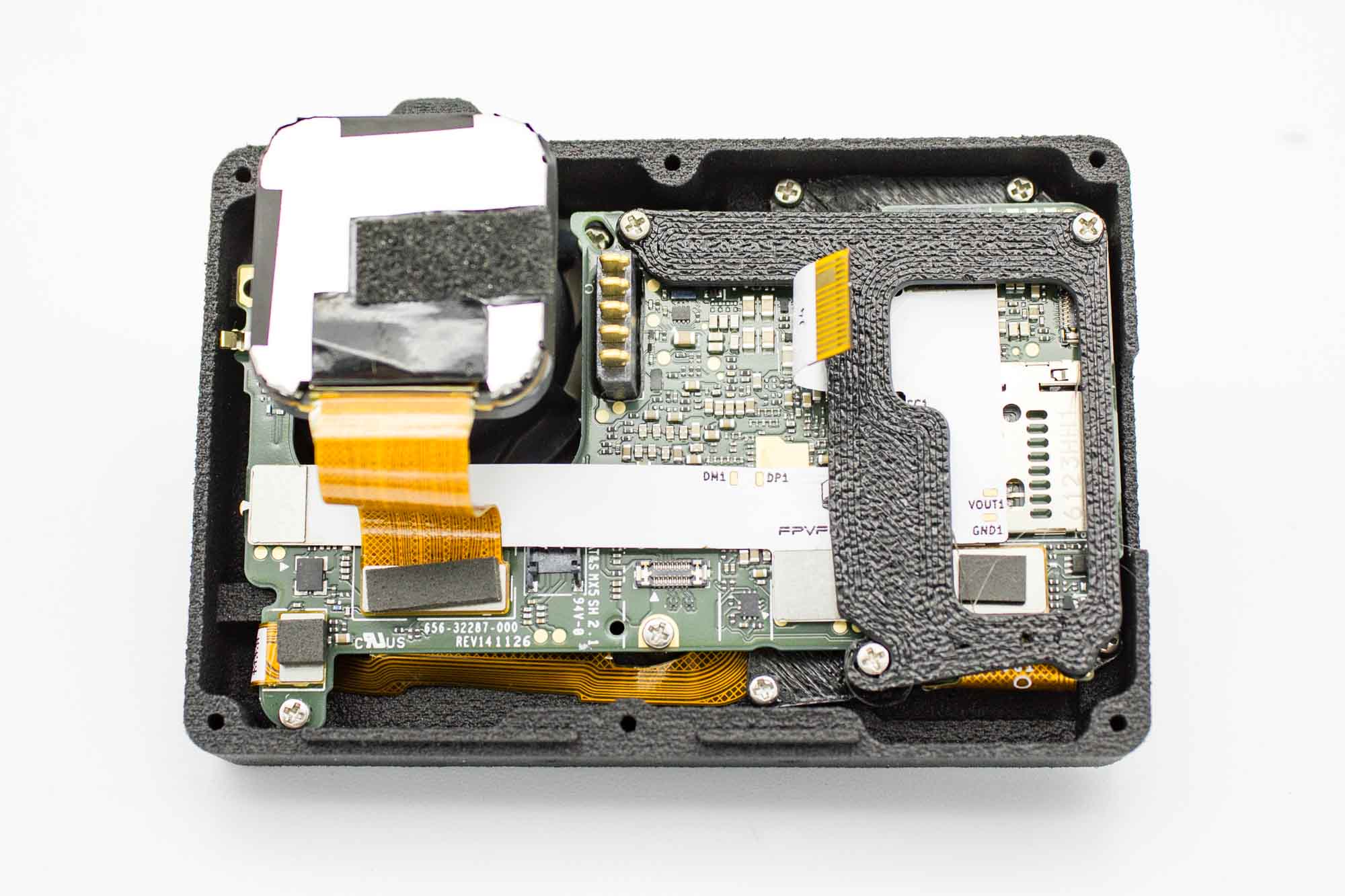
- Position the 3D printed BEC holder over the mainboard as shown.
- Secure the two upper mounting points with two M1.4 x 6mm screws.
- Secure the lower mounting point with one M1.4 x 4mm screw.
- Keep the free end of the white FPC accessible.
- Check that the holder does not pinch any ribbon cables.
Step - Connect the BEC
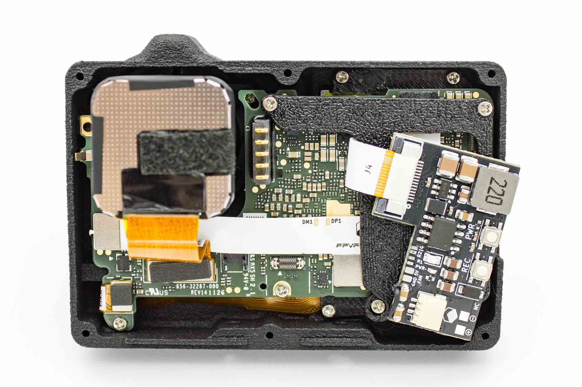
- Carefully open the locking mechanism on the BEC's FPC connector.
- Insert the free end of the white FPC in the orientation shown.
- Make sure the cable is straight and fully inserted.
- Close the locking mechanism to secure the cable.
- Position the BEC on its holder as shown in the following assembly picture.
Step - Install the Cooling Fan
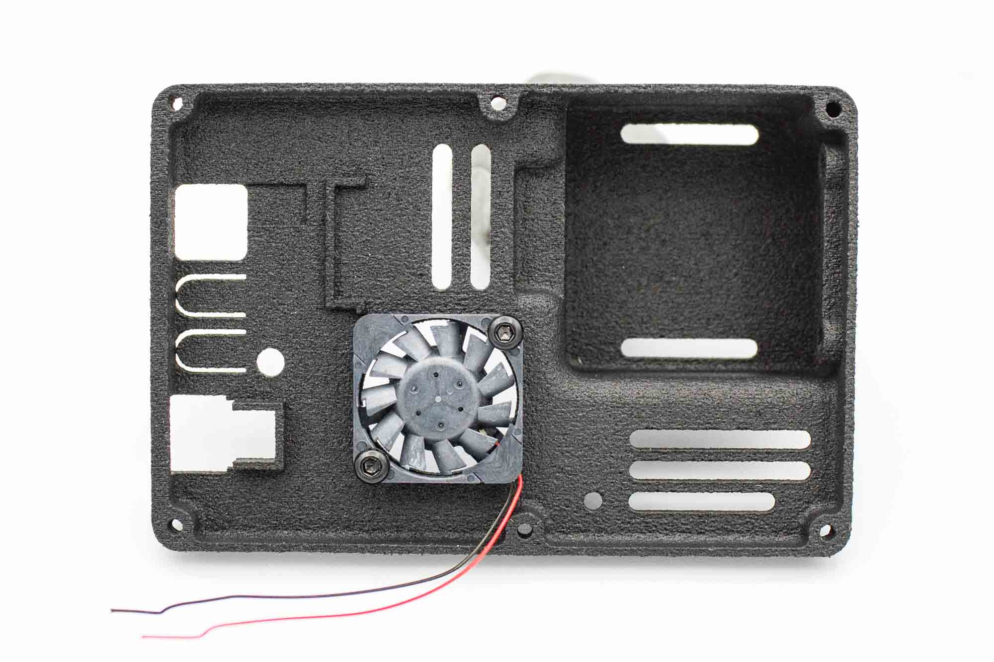
- Place the cooling fan against the inside of the back case.
- Match the fan orientation shown in the picture.
- Secure it with two M2 x 5mm screws.
- Route the fan wires clear of the blades and screw holes.
Step - Solder the Fan Wires
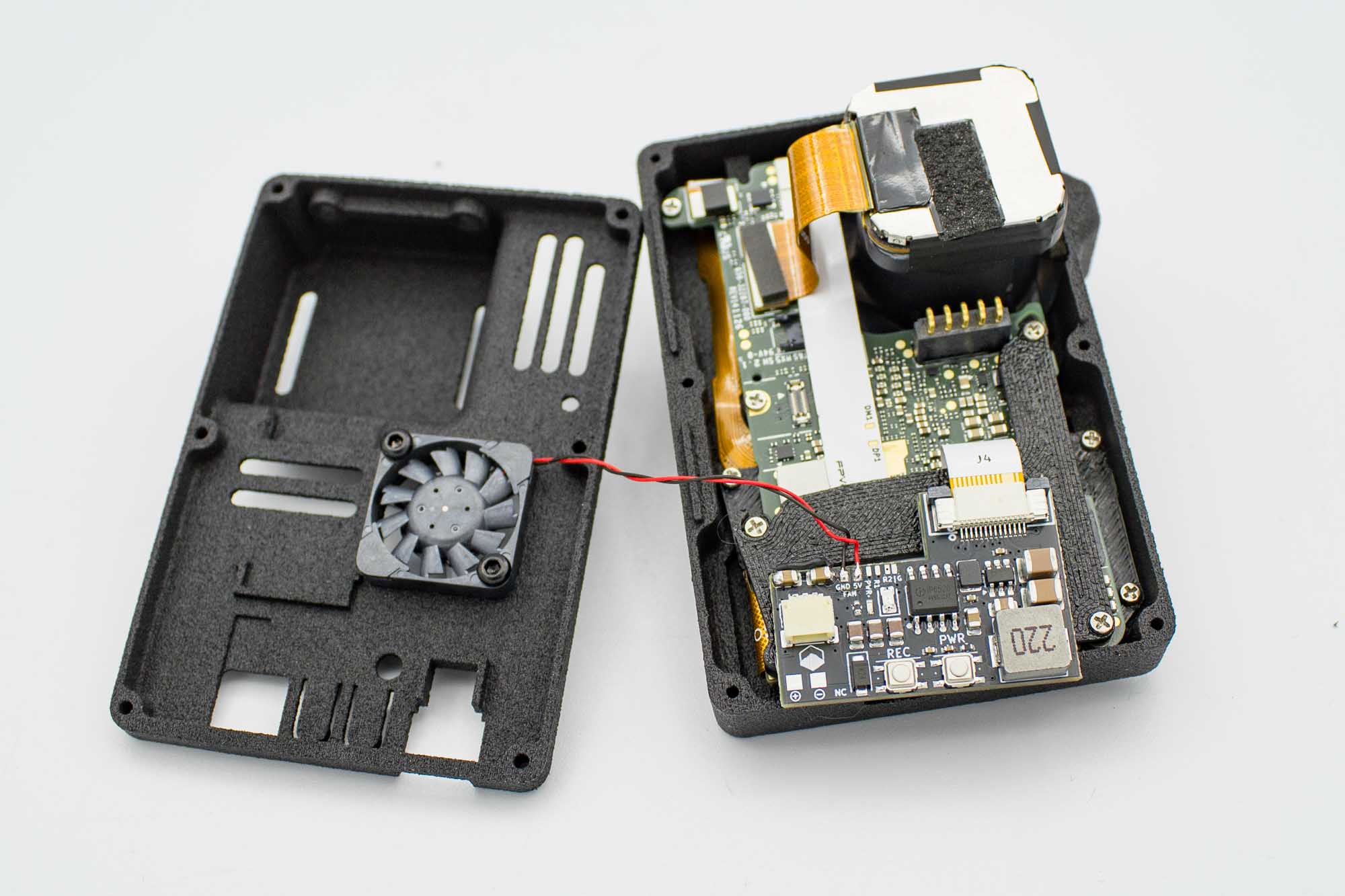
- Make sure the camera and BEC are disconnected from all power sources.
- Solder the red fan wire to the 5V pad in the FAN section of the BEC.
- Solder the black fan wire to the adjacent GND pad in the FAN section.
- Check the pad labels carefully before soldering.
- Inspect both joints for solder bridges and loose wire strands.
- Route the wires so they cannot touch the fan blades or become trapped when closing the case.
Step - Close the Case
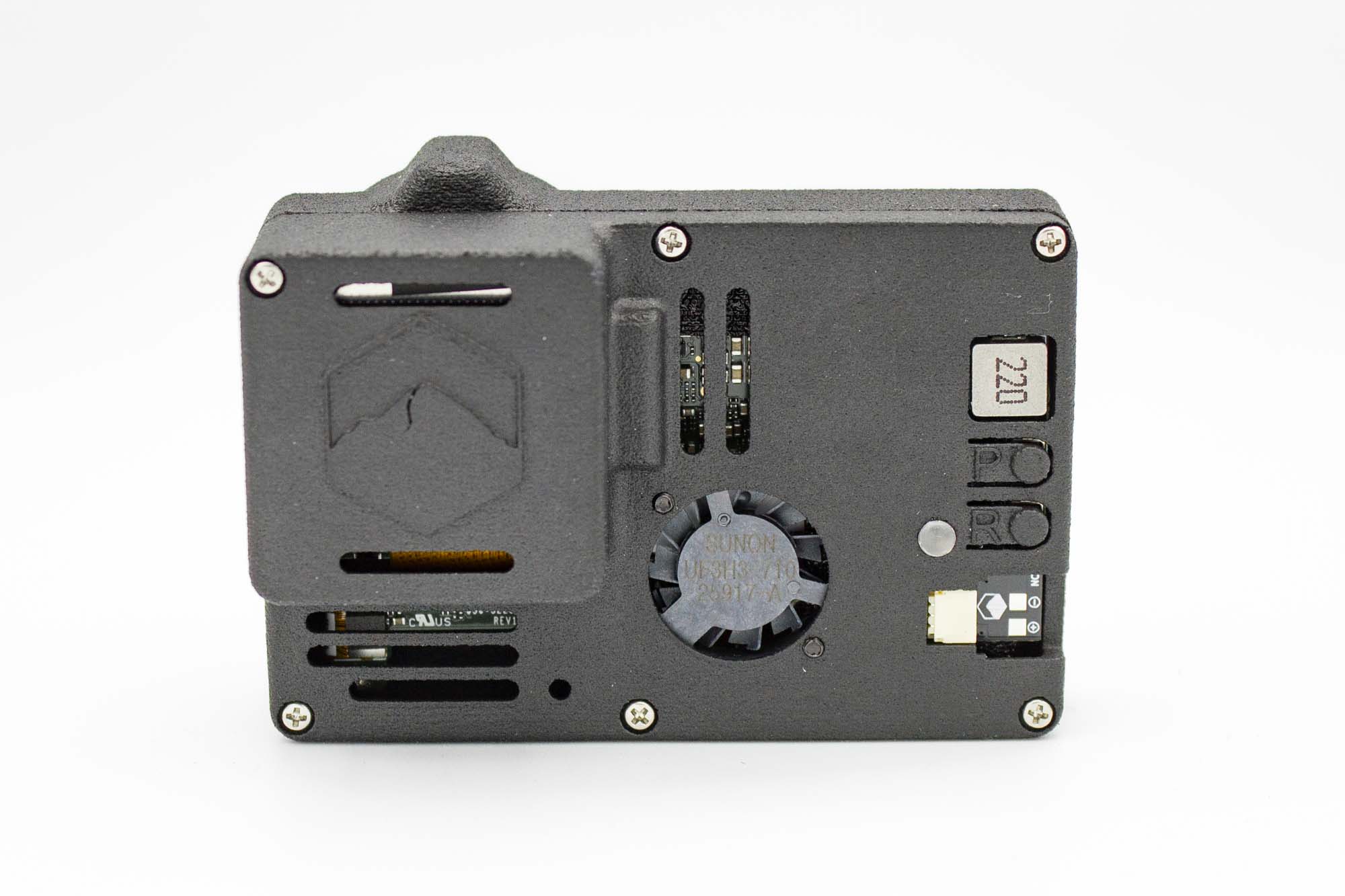
- Check that the BEC is correctly seated on its holder and aligned with the openings in the back case.
- Check all ribbon connectors once more.
- Bring the two case halves together carefully, keeping the fan wires inside and clear of the edges.
- Secure the case with five M1.6 x 8mm screws and one M1.6 x 18mm screw.
[TO CONFIRM: Specify the exact position of the M1.6 x 18mm screw, viewed from the back. Do not substitute the long screw into another position.]
- Tighten the screws gradually and evenly.
- Do not overtighten them.
- Check that the PWR and REC buttons move freely.
Step - Finished Camera
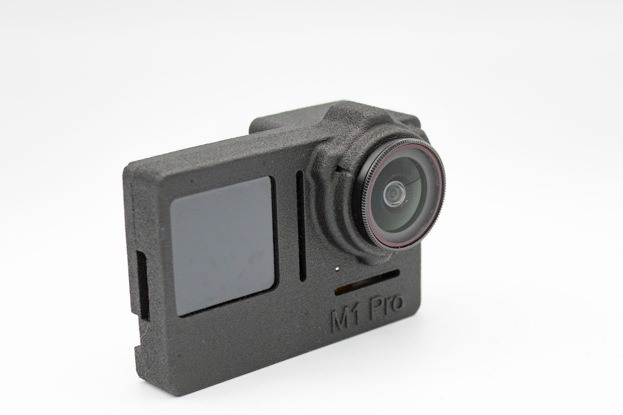
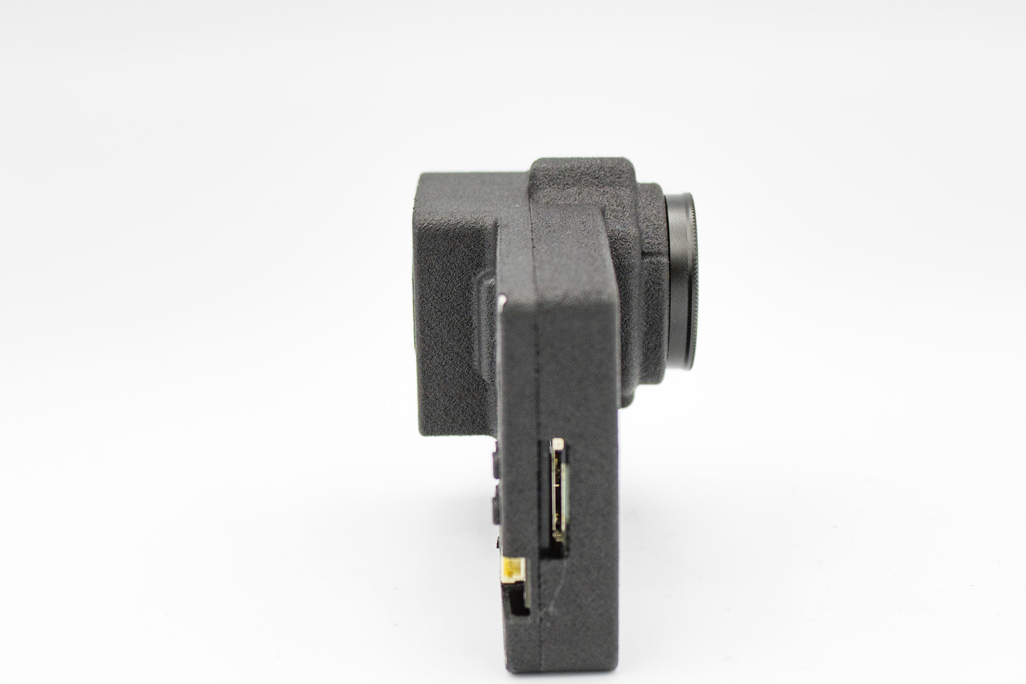
Your Naked Mission 1 Pro is now assembled. Great work! Complete the checks below before using it.
First Power-On and Final Checks
Use a smoke stopper for the first power-on. It can help limit damage from a short circuit, but it does not protect against every wiring fault or an incorrect supply voltage.
- Check the power cable polarity and make sure the supply voltage is within the BEC's specified input range.
- Connect the camera through a smoke stopper.
- If the smoke stopper trips, disconnect power and inspect the assembly before trying again.
- Power on the camera and check that the front display works.
- Check that the cooling fan spins freely.
- Test the PWR and REC buttons.
- Power off the camera before inserting the microSD card.
- Power it on again, record a short test clip, and check the saved video and audio.
BEC Power Pinout
[TO CONFIRM: Add the Mission 1 Pro BEC input voltage range, power connector pinout, and wiring diagram before publishing.]