This is an old revision of the document!
Table of Contents
NakeX 2.5 Frame Build Manual
Introduction

Welcome to the NakeX 2.5 Frame Build Manual. This guide will walk you through the complete assembly process step by step.
Step 1 – Standoffs
• Install M2x22 mm standoffs using M2x6 mm screws
• Ensure the press nut is oriented in the same direction as the standoffs
Step 2 – FC to Air Unit Adapter

• Choose the correct FC-to-Air-Unit adapter for your AIO flight controller
• The image shows both options
• (The lower adapter is shown upside down for demonstration purposes)
• Install the adapter on top of the AIO
Step 3 – TPU Antenna Mount & Spacers

• Install the TPU antenna mount on the rear standoffs
• Add the TPU spacers
• Ensure the antenna mount is oriented correctly, as shown above
Step 4 – Front Standoffs & Camera Mounts

• Install two M2x22 mm standoffs using M2x6 mm screws
• Ensure the press nuts face the same direction as the standoffs
• Push the two TPU camera mounts onto the standoffs
Step 5 – Frame Assembly

• Join both frame parts together
• Secure using M2x6 mm screws
• Do not tighten the camera mounts yet
Step 6 – GoPro Mount

• Install the GoPro mount
• Secure with two M2x8 mm screws
Step 7 – TPU Wire Mount

• Install the TPU wire mount
• Use one M2x8 mm screw through the third hole of the TPU GoPro mount
Finish
Congratulations! Your NakeX 2.5 V2 Frame is now fully assembled and ready for electronics installation.
NakeX 2.5 Complete Build Manual
Step 1 – Top Plate & Standoffs

• Install the standoffs onto the top plate
• Secure using M2x6 mm screws
Step 2 – Motor Installation

• Install all motors
• Secure with M2x5 mm screws
Step 3 – Conformal Coating (Bottom Side)

• Apply conformal coating to the bottom side of the flight controller
• Only do this if you do not plan to solder anything additional like GPS or LEDs on that side
Tip: A UV lamp makes it easy to see where coating has already been applied. Be careful not to coat any connectors or plugs.
Step 4 – Install Flight Controller

• Mount the FC using M2x12 mm screws
• Use the spacers supplied with the FC
• Ensure 1–2 mm clearance between the FC and the carbon plate
Direct contact with carbon fiber may short the FC and destroy it when powered.
• Pre-tin the motor wires and power pads
Soldering setup:
• Temperature: 450 °C
• Solder: TBS solder (recommended)
Step 5 – Motor Wire Preparation


• Cut motor wires to length
• Ideal length: about mid-FC position when routed straight along the arms
• Leave a little slack to protect pads in a crash
• Strip approx. 2 mm insulation
• Twist and pre-tin the wire ends
Step 6 – Motor Wire Soldering

• Tape the motor wires neatly to the frame
• Solder the wires to the ESC pads
Step 7 – Capacitor Preparation

• Trim capacitor legs to approx. 3 mm
• Solder 20 AWG wires to the legs
• Polarity:
– Short leg = –
– Long leg = +
• Insulate connections using shrink tube
Step 8 – Capacitor Installation

• Solder the capacitor to the FC power pads
• Align it straight and centered on the plate, as shown
Step 9 – Main Power Wires

• Solder 16 AWG power wires to the FC
• Length should be slightly longer than the frame
Step 10 – Naked Action Cam Power


• Cut the Naked Action Cam power wire to 10–11 cm
• Solder it to the FC power pads
This step requires precision — take your time to form a clean, shiny solder joint.
Step 11 – Conformal Coating (Top Side)


• Apply conformal coating to the top side of the FC
• Avoid all connectors and buttons
Step 12 – TPU XT30 Mount

• Install the TPU XT30 mount on the rear standoffs
Step 13 – XT30 Connector Preparation


• Solder the PCB plate onto the male XT30 connector
Step 14 – XT30 Power Wiring

• Cut power wires to length
• Solder them to the XT30 connector
Step 15 – Insulation

• Apply liquid rubber to all exposed power solder joints
Step 16 – Receiver Preparation


• Cut receiver wires to approx. 5 cm
• Solder the wires
• Bend the antenna slightly
• Cover everything with shrink tube
• Ensure the bind button remains accessible
Step 17 – Receiver Installation

• Install the receiver
• Apply shrink tube over:
– Capacitor
– Power wires
– Receiver
• Secure the assembly by screwing in the XT30 PCB plate
Step 18 – TPU VTX Mount

• Install the TPU VTX mount on the DJI O4 / O3 air unit
• Use M2x4 mm screws
Step 19 – VTX Installation

• Mount the VTX on top of the FC
Step 20 – O4 Antenna Modification

• Remove the four screws from the O4 air unit
• Carefully lift the cover
• Remove the U.FL antenna connectors
These connectors are extremely delicate — proceed slowly.
Step 21 – Antenna Routing

• Push the antennas through the TPU mount and shrink tube
• Using pliers to gently open space can help
Step 22 – Reassembly

• Reconnect the antennas
• Reinstall and secure the O4 top cover
Step 23 – Rear TPU Spacers

• Push the TPU rear spacers into place
Step 24 – Camera Installation

• Install the O4 camera into the TPU camera mount
• Use a zip tie to shorten excess cable for a clean layout
Step 25 – Final Connections

• Connect the O4 air unit to the FC
Step 26 – Bottom Plate

• Install the CFK bottom plate using M2x6 mm screws
• Route the receiver antenna between the rear standoffs
Step 27 – Antenna Securing

• Secure the receiver antenna to the frame using zip ties
Step 28 – Action Cam Mount

• Install the TPU action cam mount
• Secure with M2x8 mm screws
Step 29 – Battery Pads

• Cut battery pads into two thin, even strips
• Install lengthwise as shown
Benefits:
✔ Reduced weight
✔ Excellent battery grip
✔ Improved airflow to electronics
Finish
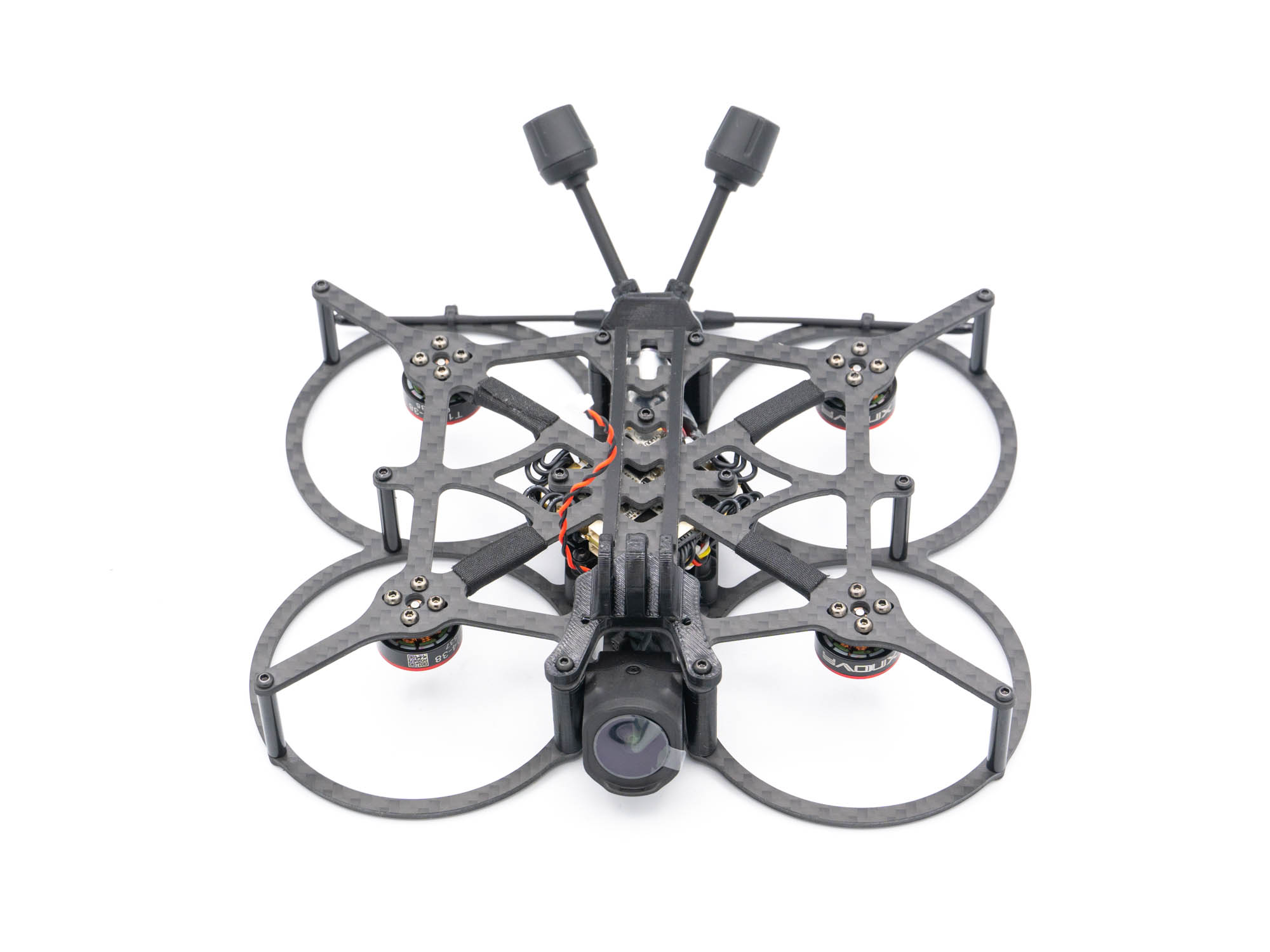
Congratulations! The major build work is complete. All that’s left is Betaflight configuration and minor ESC setup, install the props — and your NakeX 2.5 is ready to fly.