This is an old revision of the document!
Table of Contents
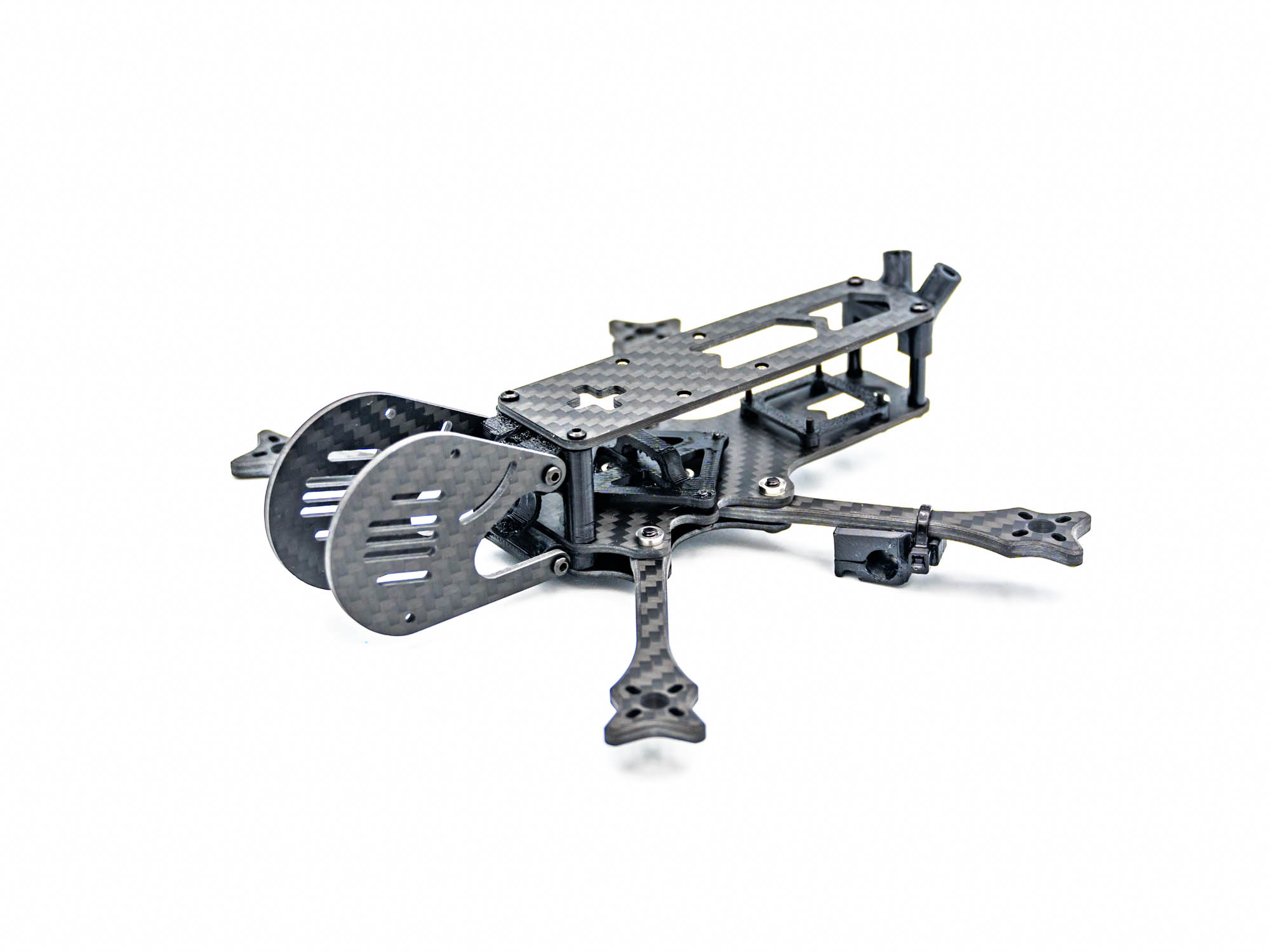
FlowX Mini V2 Frame Build Manual
Introduction
Welcome to the FlowX Mini V2 Frame Build Manual. This guide will walk you through the complete assembly process step by step.
Step 1 – Mount Arms on Bottom Plate

• Place the bottom plate on a flat surface
• Mount the arms as shown
• Secure using M3x10 mm screws
Step 2 – Middle Plate

• Add the middle plate
• Align all arms correctly
• Tighten the screws to lock the arms in place
Step 3 – TPU Bottom Pod Mount

• Press an M2x20 mm standoff into the TPU bottom pod mount
• Insert the mount into the gap between the bottom plate and middle plate
• Secure with two M2x8 mm screws
Step 4 – TPU RX Mount

• Mount the TPU RX mount above the AIO
• Secure using M2x12 mm screws
Step 5 – TPU VTX Mount

• Install the TPU VTX mount using M2x5 mm screws
• Place the DJI O4 / O3 unit on top of the mount
Step 6 – TPU Antenna & GPS Mount

• Install two M2x20 mm standoffs using M2x8 mm screws
• Place the TPU antenna mount as shown
Optional: • If using a GPS, install the TPU GPS mount beneath the antenna mount
Step 7 – Prepare TPU Pod Top & Capacitor Mount

• Press M2x20 mm standoffs into the designated holes
• Prepare both the TPU pod top mount and capacitor mount
Step 8 – Install Pod Mount on Frame

• Install the TPU pod mount
• Position it at the front of the middle plate
Step 9 – Pod Plates

• Attach both pod plates
• Secure using M2x8 mm screws
Step 10 – Top Plate

• Install the top plate
• Secure with M2x8 mm screws
Step 11 – TPU RX Antenna Mount

• Install the TPU RX antenna mount using zip ties
• Slide the antenna into the mount
• Secure it with a second zip tie wrapped around the mount and arm
Finish
Congratulations! Your FlowX Mini V2 Frame is now fully assembled and ready for electronics installation.
Complete DIY Manual
 Prepare the bottom plate with M3x10mm Screws as shown above.
 Lay out the arms.
 Put on the middle. plate and tighten the screws.
 Screw on the motors with M2x10mm screws. Use blue loctite.
 Tape the motorwires neatly to the arms.
 Apply Conformal coating the bottom side of the AIO FC.
Tip: Conformal coating is visible under UV Light.
Apply Conformal coating the bottom side of the AIO FC.
Tip: Conformal coating is visible under UV Light.

 Stick M2x12mm screws through the frame plate and fix them in place with rubber donut spacers.
Install the rubber grommits in the fc mounting holes and mount it on the frame.
Stick M2x12mm screws through the frame plate and fix them in place with rubber donut spacers.
Install the rubber grommits in the fc mounting holes and mount it on the frame.
 Cut and pre-tin the motorwires. There should be some slack.
 Solder the motorwires to the ESC pads.


Cut the main powerwires to about 10cm and pretin both ends.
 Solder the main power wires to the fc power pads.


Prepare the front bottom TPU mount by pushing a M2x20mm Standoff into the designated hole.
 Push the front bottom TPU mount into the frame and stick M2xScrews through.
 Screw on M2x20mm Standoffs on the exposed screwends.
 Install M2x20mm Standoffs with M2x8mm Screws on the rear of the frame.

Prepare the TPU top pod&capacitor mount by pushing in a M2x20mm Standoff.


Prepare the capacitor by stripping a bit of insulation off the wires, wrapping them around the cap legs tightly and then soldering them. Black=Ground/Minus → Short leg Red=Plus → Long leg Then cut off the excess legs
 Apply liquid rubber/plastidip on the exposed solderjoints.


Push the capacitor into the tpu mount and install it in the front of the frame.
 Cut the capacitor wires to length and solder them to the fc power pads.


Cut and solder the naked action camera power wire also to the fc power pads. This step can be kind of hard so take your time to create a nice solderjoint.


Cut two pieces of shrink tube and put them on the main powerwires.
 Cut the powerwire to length and solder the ends to the XT30 connector.
Insulate the solderjoints with the shrinktube.
Cut the powerwire to length and solder the ends to the XT30 connector.
Insulate the solderjoints with the shrinktube.

Now that everything is soldered to the fc, apply conductive coating to the top of the fc.


Prepare the Receiver by pretinning the solderpads.
 Solder the rx wires and install the rx antenna with a small bend so the bind button is accessible.
Then put shrinktube over it.
Solder the rx wires and install the rx antenna with a small bend so the bind button is accessible.
Then put shrinktube over it.


Install the TPU fc cover and mount the rx on top of it. Use a cover provided that fits your fc the best.


Install the rx antenna on the back left arm with the TPU RX antenna mount and two zipties.
 Push on the TPU GPS mount on the rear standoffs.
 The next step is preparing the GPS wire for installation.


The top right picture is for referencing the length. The gps wire should reach from the connector of the fc to the rear end of the frame. Cuit the wires to length, put shrinktube over the wires and solder the wires together in the right configuration. if you use the same hardware as we do, refer to the picture above.


To get maximum GPS Performance, twist the wire and shield it with copper tape. Then insulate it with shrinktube or tape.
 Install the GPS on the frame and plug the connector to the fc.
 Secure the GPS module with shrinktube or tape.
 Screw on the TPU O4/O3 Mount with M1,6x8mm Screws.